17
RS485 Communication Terminal: (RJ45 port) follow MODBUS 485 protocol, for
communication between battery system and inverter.
CAN Communication Terminal: (RJ45 port) follow CAN protocol, for communication between
battery system and inverter.
RS232 Communication Terminal: (RJ45 port) for manufacturer or professional engineer to
debug or service. The Pin1&2(12Vdc+/-) is dedicated for Sunny Boy Storage Enable Line
design.
Link0/Link1 Communication Terminal: (RJ45 port)for multi-groups operation using only,
connecting from first BMS Link 1 to second BMS Link 0, then from second BMS Link 1 to third
BMS link 0(if has), all the way to the last BMS Link 0. The BMS with Link Port 0 EMPTY is
defined as the Master string, which further communication with the inverter or upper
controller.
For multi-groups operation, please firstly make sure the communication cable between
multiple BMSs are properly connected between Link 1 and Link 0, before the start up.
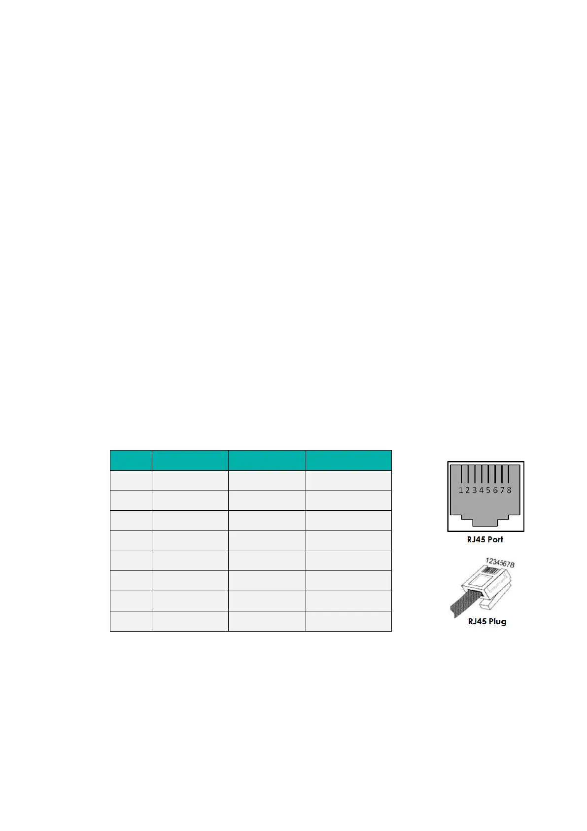
Definition of RJ45 Port Pin