Enforcer: Installation Manual
Page: 6
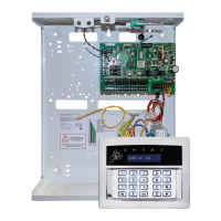
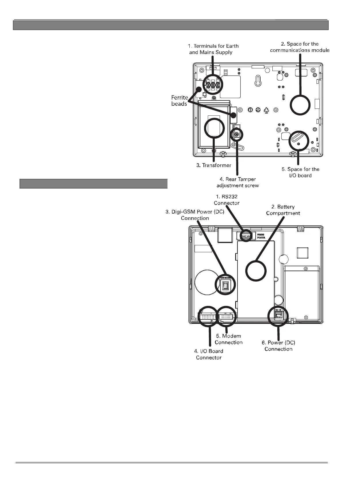
3.2 Inside of the Enforcer: Rear
1. Terminals for Earth and Mains Supply.
2. If a modem is required (DIGI-PSTN, DIGI-
PSTN/VOICE, DIGI-GPRS, DIGI-LAN or DIGI-WI-
FI) then this space is used to install them.
3. The transformer is situated in a housing.
4. The rear tamper adjustment screw is used if
the tamper from the front of the Enforcer isn't
sitting flush to the back plate - this may happen
if the Enforcer is installed on an uneven surface.
5. If an I/O board is installed, then this space is
used to install it.
3.3 Inside of the Enforcer: Front
1. RS232 connection for Up/downloading to
the InSite software.
2. Where the control panel battery is located.
3. The power connection for a communications
module if connected.
4. The connection for an I/O board if
connected.
5: The connection for a communication module
to be installed.
6: The power connection (+15V DC) for the
Enforcer.
 Loading...