Chapter 2
2 - 1
Chapter 2
Connector Configuration
This section lists all connector pin assignment and port description on the
main-board. The situations of the connectors and ports are illustrated in
the following figures. Before inserting these connectors, please pay
attention to the directions.
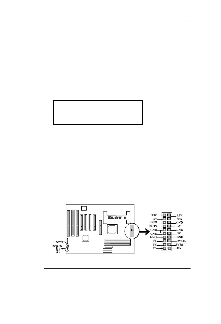
Power/Sleep LED Connector (PWRLED)
PIN NUMBER FUNCTION
1 LED Anode
2 NC
3 LED Cathode
The LED connected to “PWRLED” will blink when system in green
status and will light slightly when system in standby status.
Power Switch (POWER)
Connect ATX Power Supply connector to socket J4 first.
1. If you want to power up your system, you should turn on the
mechanical switch of ATX power supply first, then push once the button
connected to the two pin header (POWER).
2. If you want to power off your system, you need not turn off the
mechanical switch of ATX power supply , just push once * again the
button connected to the two pin header(POWER). The location of
connector is shown as below figure:
*Note: If you change “soft-off by PWR-BTTN” from default “Instant-off”
Secs”, you will have to press the power button for more than 4
 Loading...