Version: 13. September 2004
29
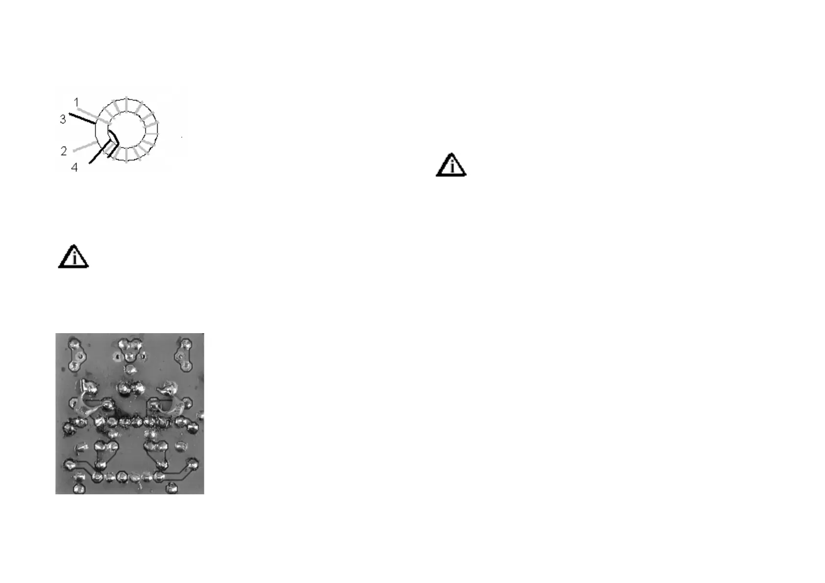
isn’t difficult either. This time it isn’t done with a tap, but with a proper
secondary. Begin with the primary, 26 turns of 0.3 mm lacquered copper
wire (AWG 28). Now put on the secondary as shown in the drawing. The
secondary is ended at point 3.
[ ] L2 Amidon T37-2
L3 is identical to L2, apart from being a mirror
image, to avoid long pc board lines. That is:
same number of turns, but winding the other
way round.
[ ] L3 Amidon T37-2
Now mount the trimming capacitors. BEWARE: Do not to confu-
se C11 with the others.
[ ] C4 2,5-60pF Film trimmer 7mm Diameter (black)
[ ] C11 2,0-45pF Film trimmer 7mm Diameter (violet)
[ ] C13 2,5-60pF Film trimmer 7mm Diame-
ter (black)
[ ] C14 2,5-60pF Film trimmer 7mm Diame-
ter (black)
Now something unusual, but not special: 2
capacitors are to be mounted on the solder
side of the board.
[ ] C22 150pF on solder side 150p/n15
[ ] C23 150pF on solder side 150p/n15
Now we just have to put in the two connec-
tors to finish the band module. Mount them and put all trimmers in centre
position.
[ ] Connector strip A
[ ] Connector strip B
[ ] Trimmers in centre position
Test Section 8
1. Visual inspection (see Section 1)
2. Resistortest (see Section 1)
[ ] Put a Bridge between pin 47 and pin 18
[ ] Put a band module activation PIN to +10C
[ ] Insert the bandmodule into the activated slug
The activation pins vor each band module are on the main board.
Which one you use is on yours, the bandmodules are all in parallel
but only one is actually activated by its corresponding activation pin.
[ ] Connect rotary encoder to DDS
[ ] Apply power as in Section 1 test.
3. Smoke test (see Section 1)
4. Functional test
The complete PLL should work now. Test the band set oscillator (VXO) first.
With a link wire and a short wave receiver, the oscillator should be loud at
11 MHz.
Hook up a digital volt meter to the connection between R3 and R4 (main
board E7). If the voltage is close to 0 or 8 Volts, the PLL isn’t working yet.
Turn trimmer C11very slowly. At some position of the trimmer the PLL will
lock, and the voltage can be adjusted by the trimmer between 2 and 6
Volts. Adjust the trimmer to an occurrence of 2 Volts. If you hold the link
wire near transistor T2, you should hear a strong signal on the SW-Receiver
at 15.030 MHz, +/- 2 kHz. If you are using the Speakys frequency counter it
displays 15,030 MHz, too. If you own an oscilloscope, you can see the VCO
signal at IC1 pin 6. With trimmer P1 set it to some 250 mVpp. If you use an
RF probe, set it to 100 mVeff. With the calibrated probe of QRPproject you
have to adjust a value, which you can take from the SW-Calibration-Curve
for a nominal value of 250 mVss.
L1 is so broad banded, that it doesn’t demand tuning. But set it to a maxi-
mum signal at IC2 pin 11, anyhow.
That’s that. The PLL works. Remove the bridges and go on to section 9.