32 7080-163D August 3, 2018
MT. VERNON E2-C
EXHAUST
TEMPERATURE
SERIAL PORT
(SERVICE ONLY)
POT SET TEMP VCC
POT SET TEMP GND
POT SET TEMP SIG
POT FEED ADJUST VCC
POT FEED ADJUST GND
POT FEED ADJUTS SIG
LED RED
LED AMBER
LED GREEN
FUSE
M
M
M
110 V
LINE
NEUTRAL
IGNITER
FEED MOTOR
EXHAUST
BLOWER
CONVECTION
BLOWER
VACUUM
SWITCH
SNAP
DISC
BLACK
WHITE
PURPLE
PURPLE
BLUE
BLUE
ORANGE
WHITE
BLACK
BLACK
SNAP
DISC
HOPPER
SWITCH
THERMOSTAT SIG
THERMOSTAT GND
THERMOSTAT VCC
SPEED SENSOR
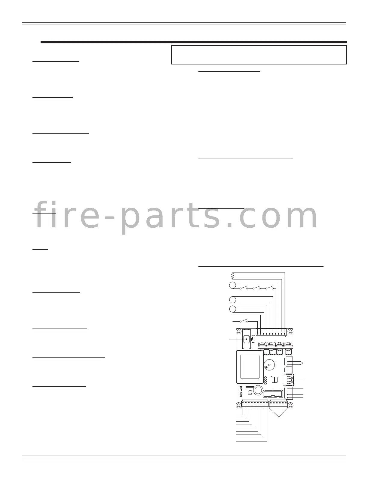
Figure 32.1 - Control Board Schematic
11. Overheat Snap Discs
There are two overheat snap discs located within the
electro-mechanical cavity of the appliance. One is
mounted on the back of the drop tube in the center of the
appliance; the other is mounted in the RH side between the
rebox and cast side panel. Both snap discs have a reset
button. If the re tries to burn back into the feed system,
the drop tube snap disc will shut the appliance down. If
there is not enough circulation from the convection blower
the second snap disc will shut the feed system off. Either
sensor must be manually re-set if tripped. Disconnect
power before resetting.
12. Exhaust Probe - Exhaust Blower
The exhaust probe is a temperature-sensing device
attached to the exhaust blower housing via screw and
clamp. It provides sympathetic exhaust temperature
feedback to the control board. In turn, the control board
uses this information to adjust its heat-output systems for
best performance.
13. Vacuum Switch
The vacuum switch is located on the right side of the
appliance under the feed motor, behind right side panel. Its
vacuum hose connects to the drop tube. This switch turns
the feed system on when vacuum is present in the rebox.
The vacuum switch is a safety device to shut off the feed
motor if the exhaust or the heat exchanger system is dirty,
plugged, or if the rebox door is open.
14. Wiring Schematic for Control Board (below)
When describing the location of a component, it is
always AS YOU FACE THE FRONT OF THE APPLIANCE.
A. Component Functions
1. Exhaust Blower
The combustion (exhaust) blower is mounted in the bottom
right rear of appliance. The blower is designed to pull the
exhaust from the appliance and push it out through the
venting system.
2. Control Board
The control board is located on the right side of
appliance. It controls the functioning of the appliance and
communicates with the dial control. The control board can
only be replaced by an authorized dealer.
3. Convection Blower
The convection blower is mounted at the bottom left of
the appliance. The convection blower pushes heated air
through the heat exchange system into the room.
4. Feed System
The feed system is located on the right side of the
appliance and can be removed as an entire assembly. The
hollow feed spring (auger) pulls pellets up the feed tube
from the hopper area and drops them down the feed chute
into the re pot. Reference the parts list for individual parts
in feed assembly .
5. Fire pot
The re pot is made of high quality ductile iron. The oor of
the re pot opens for cleaning and is manually operated by
the homeowner. The oor needs to return to a completely
closed position or the appliance will not operate properly.
6. Fuse
The control board fuse will blow should a short occur. The
control board will need to be replaced. DO NOT REPLACE
THE FUSE. If the control board fuse blows its TRIAC, that
portion of the circuit, will remain closed causing the motor
on that leg to run continuously at high speed.
7. Heat Exchanger
The heat exchanger is located behind the bafe and
transfers heat from the exhaust system into the convection
air chamber. Remove the cast iron bafe to access the heat
exchanger.
8. Hopper Lid Switch
The hopper lid switch is located on the right side, inside
the hopper. It switches the feed motor off if the hopper lid is
open.
9. Igniter (Heating Element)
The igniter is mounted on the base of the re pot.
Combustion air travels over the red hot igniter creating
super heated air that ignites the pellets.
10. Power Receptacle
The power receptacle is located below the control box on
right side. Install the power cord (supplied in the appliance
component pack) to the appliance receptacle. Prior to
installing, check the wall receptacle for 120 volt, 60 Hz
(standard current). Make sure the outlet is grounded and
has the correct polarity. A good quality surge protector is
highly recommended to protect the appliance electronics.
E
5 Reference Materials
f i r e - p a r t s . c o m