2-8 Description
62-0162-01
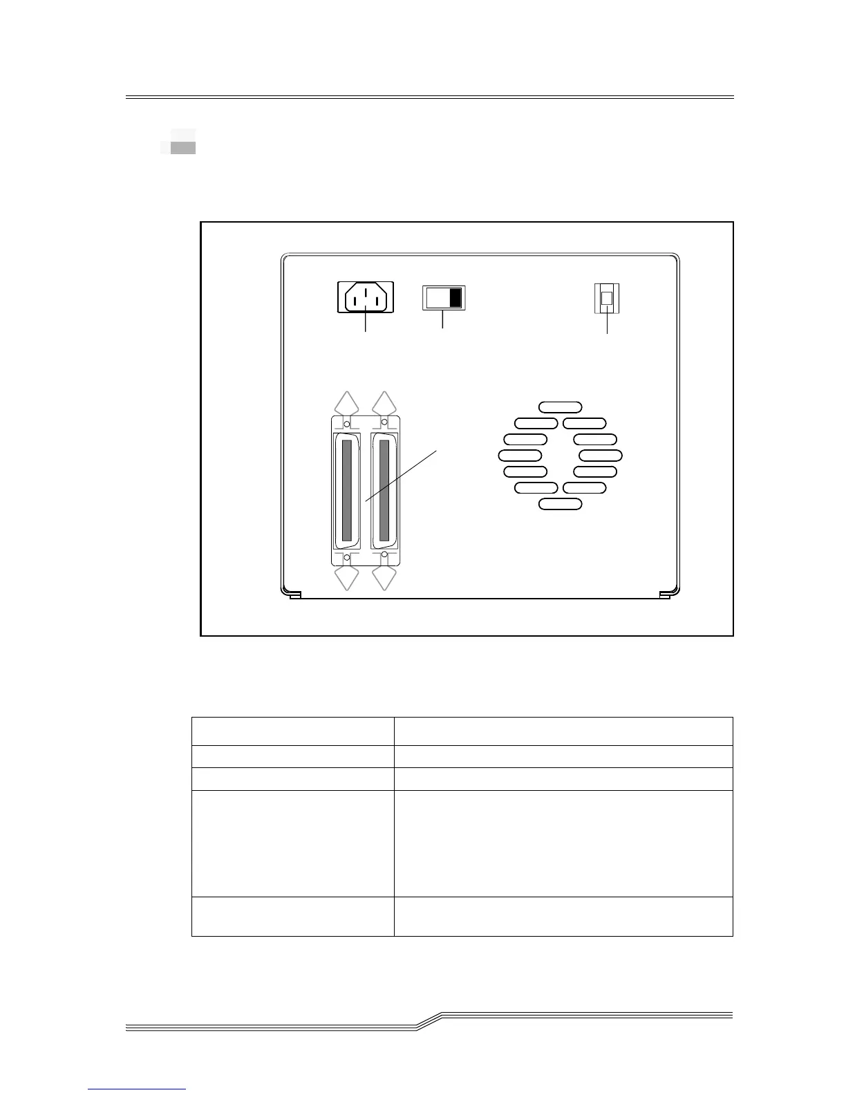
Rear Panel Controls and Connectors
Figure 2-3 on page 2-8 shows the controls and connectors
located on the rear panel of the 7000DLT Series.
Figure 2-3 7000DLT Series Rear Panel
Table 2-5 describes the controls and connections.
Table 2-5
Rear Panel Controls and Connectors
Control or Connector Purpose
Power Switch Turns power to the unit on and off.
AC Power Connector Receptacle for AC power cord.
SCSI Channel Connectors Connections for the interface cable that connects the
unit with the host computer and/or to other devices
on the SCSI channel. The interface cable can be
attached to either connector.
The 7000DLT, a fast, wide SCSI-2 device, uses a 68-
pin high density SCSI device connector.
SCSI ID Switch Used to select the SCSI ID for the DLT drive. Factory
set at 0.
SCSI Channel
Connectors
SCSI ID
Switch
Power
Switch
AC Power
Connector
3