Initial Configuration 37
DXi6701/DXi6702
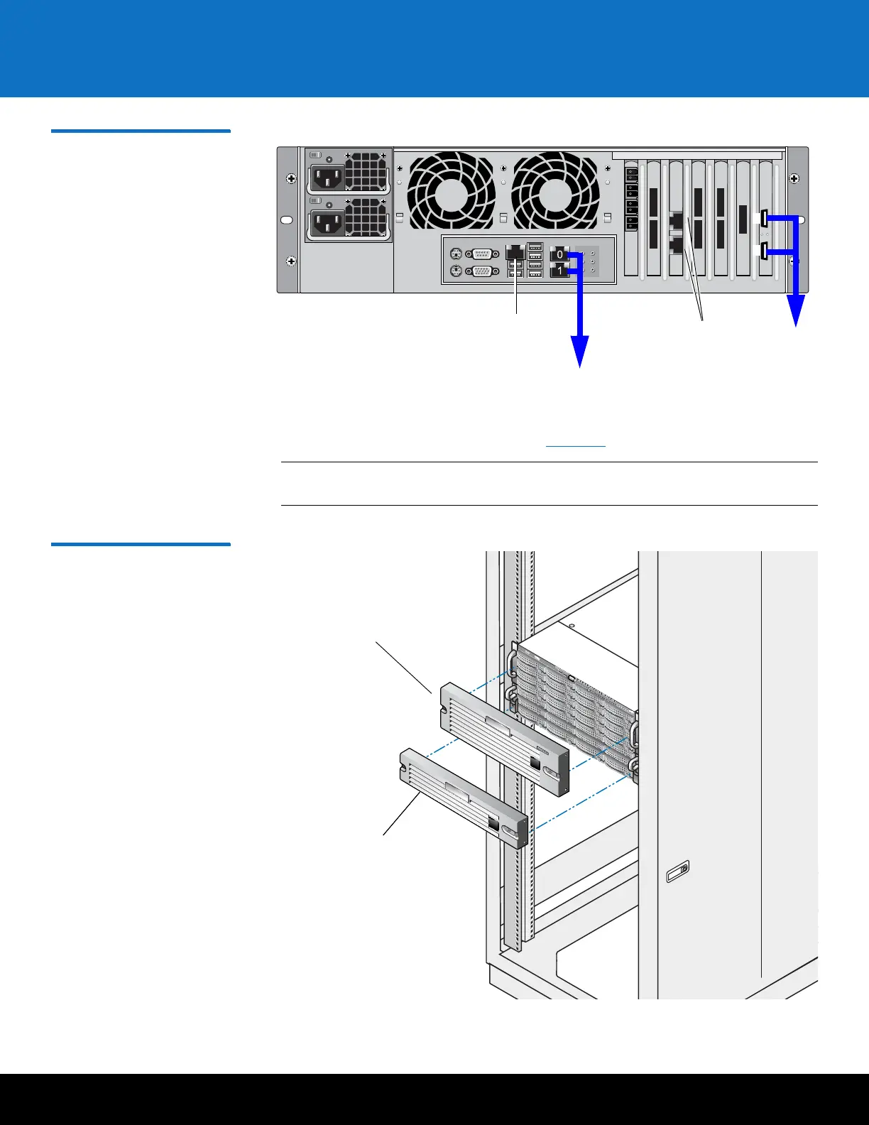
Figure 25 Connecting the
Ethernet Cables (DXi6702)
4 Install a bezel on the front of the DXi6701/DXi6702 node and expansion module(s).
The bezel snaps into place on the front of the DXi6701/DXi6702 node to prevent the
removal of the system from the rack (see
Figure 26).
Note: The keys that lock and unlock the front bezel are located in the accessory
kit.
Figure 26 Installing the Front
Bezels
123
456
4
5
1
0
2
3
10 GbE
Ethernet
ports
Service ports (not
for customer use)
1GbE Motherboard ports
Not used
DXi6701/DXi6702 node bezel
Expansion module bezel
Expansion module bezel