Do you have a question about the Queclink GV55 and is the answer not in the manual?
GV55N Protocol Reference details the air protocol interface between the device and backend server.
Defines common abbreviations used in the GV55N User Manual, including technical terms and signals.
Confirms all included items with the GV55N device before starting the setup process.
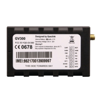
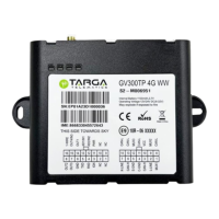
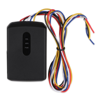
Details the components included with the GV55N, such as the locator and cables.
Explains the sequence and definition of the 6-pin interface connector for power and I/O.
Defines the color coding for the GV55N user cable to ensure correct pin connections.
Provides instructions on how to safely open the GV55N device case using a pry opener.
Details the procedure for securely closing the GV55N device case after installation.
Guides users on inserting the SIM card correctly into the GV55N, ensuring proper orientation.
Explains the process of installing the internal Li-ion backup battery for the GV55N.
Instructs on how to activate the GV55N's internal backup battery using the ON/OFF switch.
Details the VIN and GND connections for powering the GV55N, including voltage range.
Explains how to connect the IGN pin for ignition detection and its electrical characteristics.
Describes the general purpose digital inputs, their negative trigger type, and electrical characteristics.
Details the two digital outputs, their open drain type, current limits, and internal circuit.
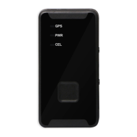
Explains the function and behavior of the GV55N's status LEDs for GSM, GPS, and power.
Illustrates the direction of the internal 3-axis accelerometer sensor for motion detection.