GV55NUsermanual
TRACGV55NUM001 ‐10‐
Table 4. Description of 6 PIN Connections
Index Description Comment
1 VIN External DC power input, 8-32V
2 GND GND
3 IGN Ignition input, positive trigger
4 IN1 Digital input, negative trigger
5 OUT2 Open drain, 150mA max
6 OUT1 Open drain, 150mA max ,with latch circuit
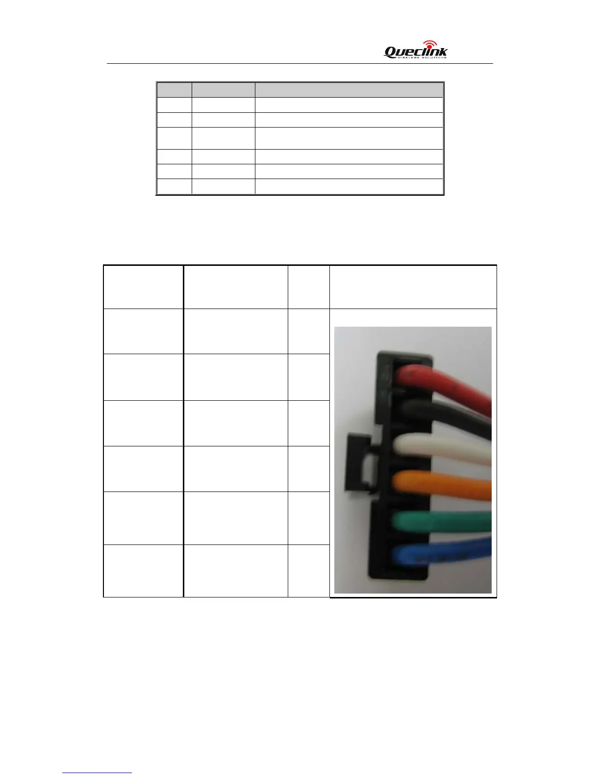
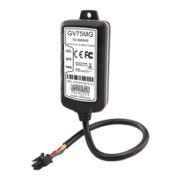
Table 5. GV55N User Cable Colour definition
Definition
Color
PIN
No
Cable
VIN Red 1
GND Black 2
IGN White 3
IN1 Orange 4
OUT2 Green 5
OUT1 Blue 6
2.4. GV55NUserCableColour