LPWA Module Series
BG96 Hardware Design
BG96_Hardware_Design 31 / 79
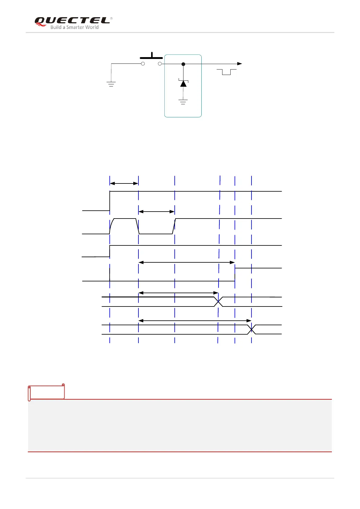
Figure 7: Turn on the Module Using Keystroke
The power on scenario is illustrated in the following figure.
V
IL
≤0.5V
VBAT
PWRKEY
≥500ms
RESET_N
STATUS
(DO)
Inactive
Active
USB
NOTE
Inactive
Active
URAT
≥ 4.8s
≥ 4.2s
≥ 4.9s
Figure 8: Power-on Timing
1. Make sure that VBAT is stable before pulling down PWRKEY pin, and keep the interval no less than
30ms.
2. PWRKEY is internally pulled up to an internal voltage in the Qualcomm chipset, and its output voltage
is the internal voltage minus a diode drop in the chipset. Therefore, the expected output voltage of
PWRKEY is 0.8V.