LPWA Module Series
BG96 Hardware Design
BG96_Hardware_Design 41 / 79
3.11. PCM and I2C Interfaces*
BG96 provides one Pulse Code Modulation (PCM) digital interface and one I2C interface. The following
table shows the pin definition of the two interfaces which can be applied on audio codec design.
Table 15: Pin Definition of PCM and I2C Interfaces
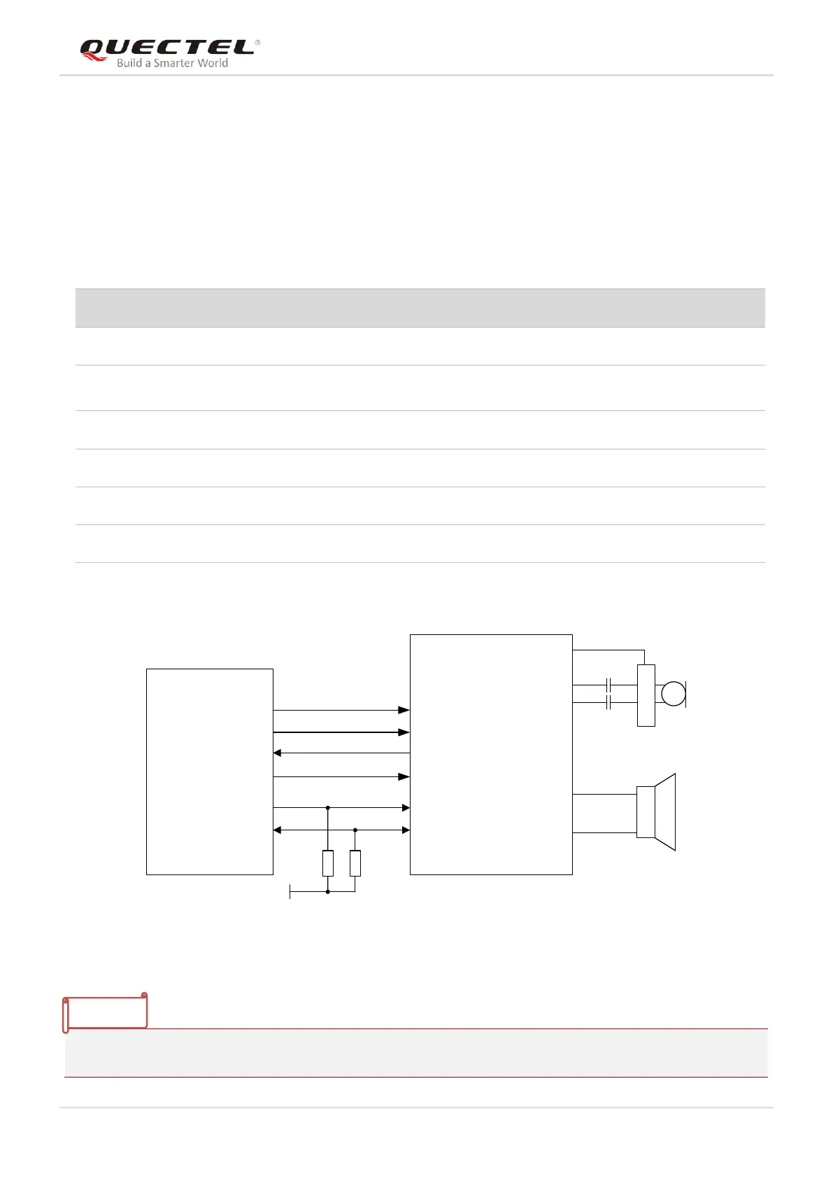
The following figure shows a reference design of PCM and I2C interfaces with an external codec IC.
PCM_IN
PCM_SYNC
PCM_CLK
I2C_SCL
I2C_SDA
Module
1.8V
4.7K
4.7K
BCLK
WCLK
ADC
SCL
SDA
BIAS
MICBIAS
INP
INN
LOUTP
LOUTN
Codec
PCM_OUT
DAC
Figure 18: Reference Circuit of PCM Application with Audio Codec
“*” means under development.
PCM frame synchronization
output
Require external pull-up to 1.8V
Require external pull-up to 1.8V