GNSS Module Series
L76&L76-L_Hardware_Design 44 / 59
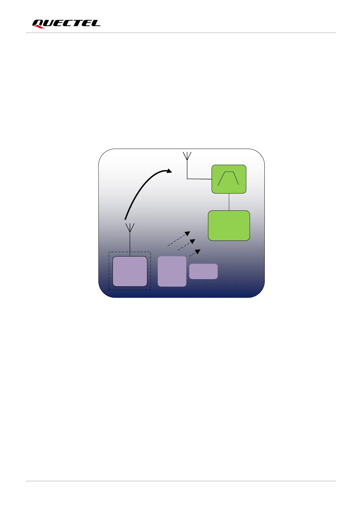
The following figure illustrates the interference source and its possible interference path. In a complex
communication system, there are usually RF power amplifiers, MCUs, crystals, etc. These devices should
be far away from a GNSS receiver, or a GNSS module. In particular, shielding should be used to prevent
strong signal interference for power amplifiers. The cellular antenna should be placed away from a GNSS
receiving antenna to ensure enough isolation. Usually, a good design should provide at least a 20 dB
isolation between two antennas. Take DCS1800 for example, the maximum transmitted power of
DCS1800 is around 30 dBm. After a 20 dB attenuation, the signal received by the GNSS antenna will be
around 10 dBm, which is still too high for a GNSS module. With a GNSS band-pass filter with around
40 dB rejection in front of the GNSS module, the out-of-band signal will be attenuated to -30 dBm.
 Loading...