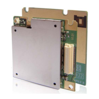
M20 Hardware Design
M20_HD_V1.01 - 3 -
3.11.1 SIM card application ..............................................................................................55
3.11.2 Design considerations for SIM card holder............................................................57
3.12 ADC..................................................................................................................................59
3.13 Behavior of the pin RI0....................................................................................................59
3.14 Network status indication.................................................................................................61
4 Antenna interface .........................................................................................................................62
4.1 Antenna installation............................................................................................................62
4.1.1 Antenna connector....................................................................................................62
4.1.2 Antenna pad..............................................................................................................63
4.2 RF output power.................................................................................................................64
4.3 RF receiving sensitivity......................................................................................................64
4.4 Operating frequency...........................................................................................................64
5 Electrical, reliability and radio characteristics .............................................................................65
5.1 PIN assignment of the module ...........................................................................................65
5.2 Absolute maximum ratings.................................................................................................66
5.3 Operating temperatures ......................................................................................................66
5.4 Power supply ratings ..........................................................................................................66
5.5 Current consumption ..........................................................................................................67
5.6 Electro-static discharge ......................................................................................................70
6 Product information .....................................................................................................................71
7 Mechanical dimension .................................................................................................................72
7.1 Mechanical dimensions of module.....................................................................................72
7.2 Footprint of recommendation.............................................................................................73
7.3 Mounting module in the host .............................................................................................73
7.3.1 Board-to-board connector.........................................................................................74
7.3.2 Mechanical dimensions of the DF12 header (without metal fitting) ........................74
7.3.3 Physical photo of the DF12 connector .....................................................................75
7.4 RF connector ......................................................................................................................76
7.4.1 Physical photo of the UF.L-R-SMT connector.........................................................76
7.4.2 Matching connector on the application side of M20 ................................................76
7.4.3 Space factor of mated connector ..............................................................................77
7.5 Top view of the module .....................................................................................................78
7.6 Bottom view of the module................................................................................................78
Appendix A: GPRS Coding Schemes .............................................................................................79
Appendix B: GPRS Multi-slot Classes ...........................................................................................80

 Loading...