M20 Hardware Design
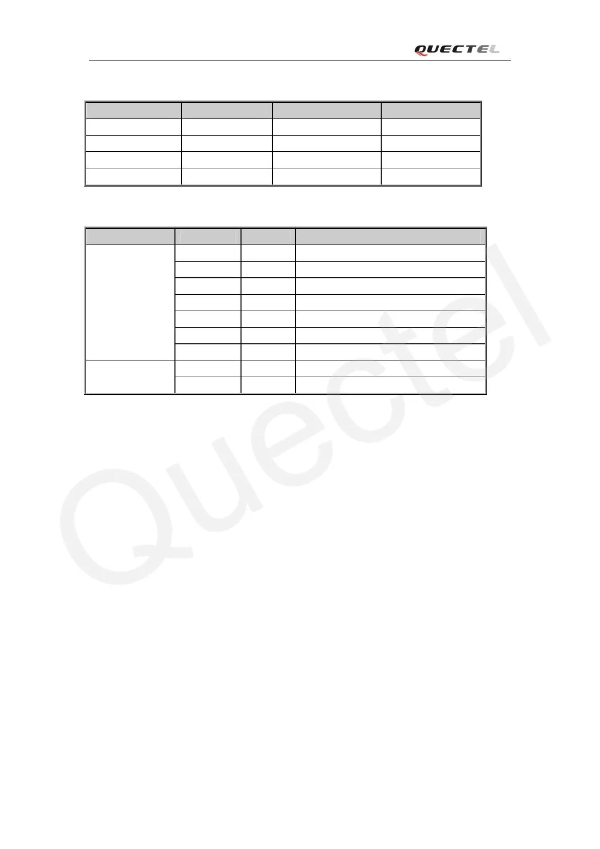
Table 14: Logic levels of serial port
Parameter Min Max Unit
V
IL
0 0.67 V
V
IH
1.67 VDD_EXT +0.3 V
V
OL
GND 0.34 V
V
OH
2.0 VDD_EXT V
Table 15: Pin definition of serial interface
Interface Name Pin Function
RI0 32 Ring indicator
RTS0 34 Request to send
CTS0 37 Clear to send
RXD0 17 Receive data of the serial port0
TXD0 15 Transmitting data of the serial port0
DTR0 35 Data terminal ready
Serial port 0
DCD0 39 Data carrier detection
RXD1 16 Receive data of the serial port1
Serial port 1
TXD1 14 Transmitting data of the serial port1
3.9.1 Function of serial port 0 & serial port 1
Serial Port 0
z Seven lines on serial interface.
z Contain data lines TXD0 and RXD0, hardware flow control lines RTS0 and CTS0, other
control lines DTR0, DCD0 and RI0.
z Use for AT command, GPRS data, CSD FAX, etc. Multiplexing function is supported at
Serial Port 0. So far only the basic mode of multiplexing is available.
z Support the communication baud rates as the following:
75,150,300,600,1200,2400,4800,9600,14400,19200,28800,38400,57600,115200
Default setting is 115200bps.
z Support the following baud rates for Autobauding function:
4800, 9600, 19200, 38400, 57600, 115200bps
After setting a fixed baud rate or Autobauding, please send “AT” string at that rate, the serial port
is ready when it responds “OK”. Autobauding is not compatible with multiplex mode.
Autobauding allows the module to automatically detect the baud rate of the data sent from the host
controller, which gives the flexibility to put the module into operation without considering which
baud rate the host application is using. Autobauding is disabled in default and can be activated by
“AT+IPR”. To take advantage of the autobauding mode, special attention should be paid to the
following requirements:
M20_HD_V1.01 - 45 -