M20 Hardware Design
GND C4
GND C5
VPP C6 Not connect
SIM_DATA C7 SIM Card data I/O
SIM_PRESENCE C8 SIM Card Presence detection
3.12 ADC
The pin ADC1 can be used to measure analog voltage. Customer can get the measurement result
through AT command “AT+QEADC”.
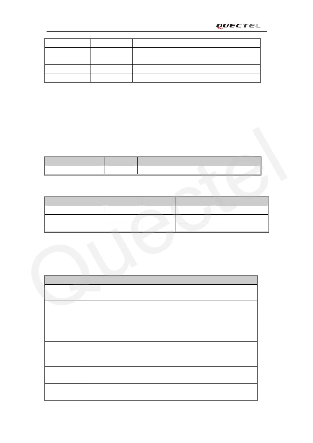
Table 23: Pin definition of the ADC
Name Pin Function
ADC1 12 Measure analog voltage
Table 24: Characteristics of the ADC
Min Typ Max Units
Voltage range 0 2.8 V
ADC Resolution 10 10 bits
ADC accuracy 2.7 mV
3.13 Behavior of the pin RI0
Table 25: Behaviours of the RI0
State RI respond
Standby HIGH
Voice calling Change to LOW, then:
(1)Change to HIGH when call is established.
(2)Use ATH to hang up the call, change to HIGH.
(3)Calling part hangs up, change to HIGH.
(4) Change to HIGH when SMS is received.
Data calling Change to LOW, then:
(1)Change to HIGH when data connection is established.
(2)Use ATH to hang up the call, change to HIGH.
SMS When a new SMS comes, The RI changes to LOW and holds low level for
about 120 ms, then changes to HIGH.
URC Certain URCs can trigger 120ms low level on RI. For more details, please
refer to the document [10]
M20_HD_V1.01 - 59 -