NB-loT Module Series
BC660K-GL-TE-B User Guide
BC660K-GL-TE-B_User_Guide 20 / 30
4. Short-circuit pin 1 & 2 of CN2, pin 3 & 4 of CN2, pin 1 & 2 of JP5 and pin 1 & 2 of JP6;
5. Insert a Micro-SIM card into J303; a NB-IoT USIM card should be selected;
6. Connect the rod antenna with the SMA connector on J304 (RF antenna connector);
7. Switch J302 (UART Switch) to the “MAIN UART TO MCU” state;
8. Connect BC660K-GL-TE-B with STM32 Nucleo-64 board via the Arduino interface. Specifically,
connect J305, J306, J307 and J308 of BC660K-GL-TE-B with CN5, CN6, CN8 and CN9 respectively.
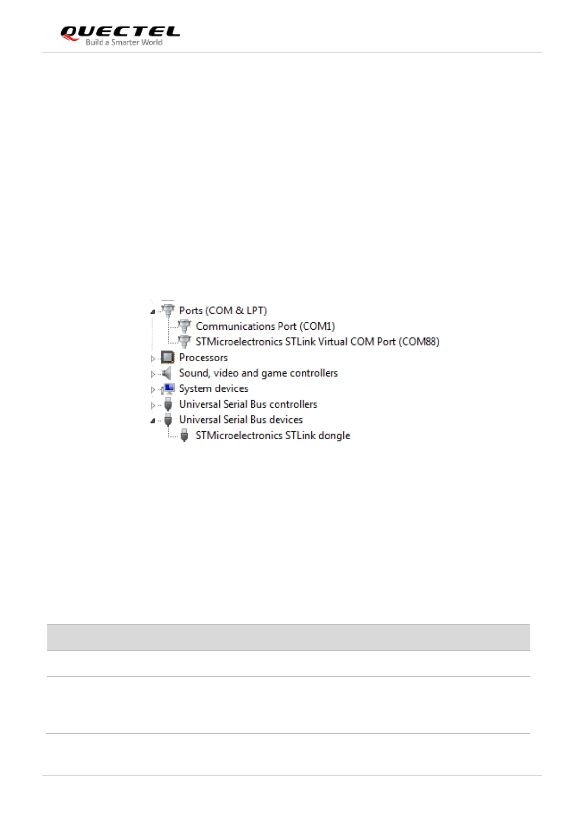
9. Connect CN1 of STM32 Nucleo-64 board with your PC via a Mini USB cable. After powering on the
BC660K-GL module, the device information will be displayed on the “Device Manager” of the PC (as
shown in the following figure).
Figure 9: ST-LINK Interface Displayed on PC
3.2.3. Description of Pin Connection
The table below shows the pin connection between BC660K-GL-TE-B and STM32-L476RG MCU, one
kind of STM32 Nucleo-64 board.
Table 3: Pin Connection between BC660K-GL-TE-B and STM32-L476RG MCU
 Loading...