Condensation in the air net cannot occur unless the air is cooled to below the dew point indicated on the
control panel.
2.3 Refrigerant flow
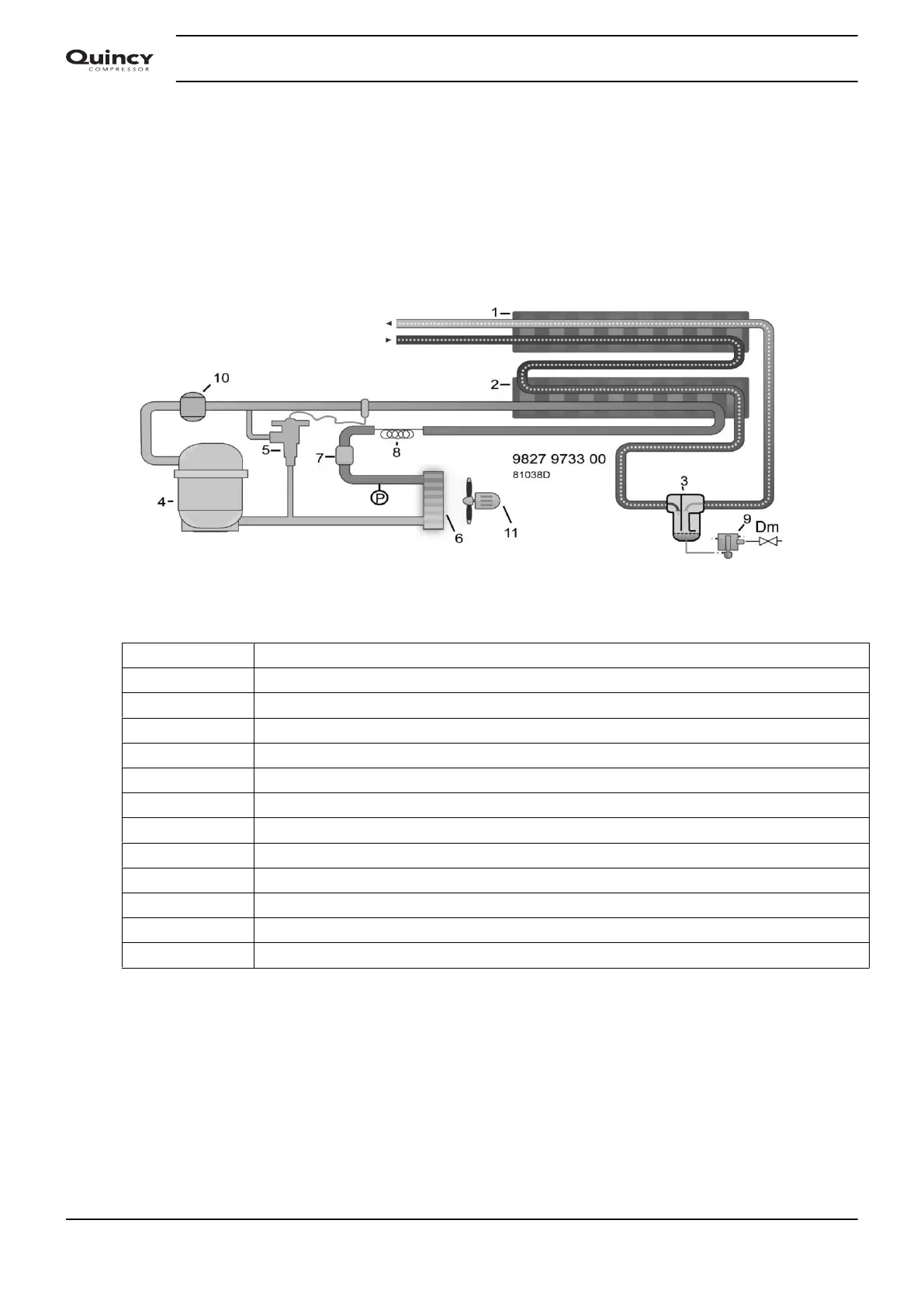
Flow diagram
Flow diagram
Name Reference
1 Heat exchanger
2 Evaporator
3 Water separator
4 Refrigerant compressor
5 Hot gas bypass valve
6 Condenser
7 Refrigerant dryer/filter
8 Capillary
9 Electronic condensate drain
10 Liquid separator
11 Cooling fan
Dm Manual drain valve
Operation
The liquid separator (10) ensures that only refrigerant enters the compressor.
Compressor (4) delivers hot, high-pressure refrigerant gas which flows through condenser (6) where the
refrigerant condenses.
The liquid refrigerant flows through dryer/filter (7) to the capillary tube (8). The refrigerant leaves the capillary
tube at evaporating pressure.
Instruction book
14 2920 7103 90



 To Next Page