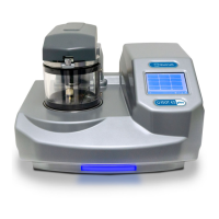
Q150T Sample Preparation System
10473 - Issue 5 12 Q150T - Instruction Manual
2.3 Connections
Installation consists of the following steps:
Connect gas supplies (see below).
Make electrical connections (see page 13).
Connect the vacuum pump (see page 15).
Install the sample stage (see page 16).
If you want to install a different insert than that supplied with your instrument, please see
page 54. If you have ordered a Q150T ES, the instrument will be fitted with the sputter
insert, unless you have specifically requested another configuration.
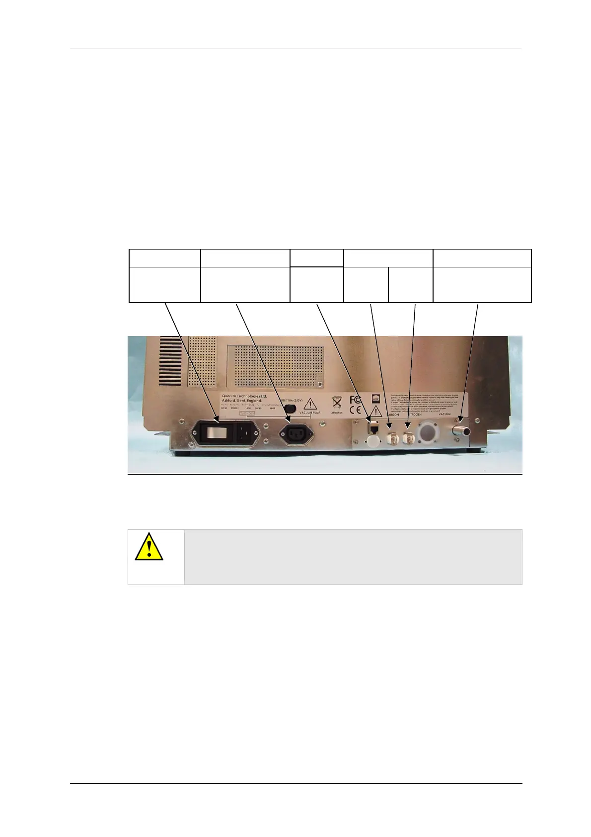
Figure 2-1 shows the location of connectors and switches on the rear panel of the
Q150T.
Figure 2-1. Q150T Rear Panel
(1). S versions only
(2). If using air instead of Nitrogen, fit filter part no. 12842 see “Gas Connections”,
below.
WARNING
UNDER NO CIRCUMSTANCES SHOULD ANY OTHER
CONNECTIONS OR OUTLETS/INLETS BE USED FOR ANY OTHER
EQUIPMENT OR SERVICES.
Power inlet with
integral On/Off
rocker switch
Power supply for rotary
pump allowing control by
instrument.
Argon
1
0.3bar
(4psi)
Nitrogen
2
0.3bar
(4psi)
Rotary Pump Vacuum
connection
GAS INLETSPUMP OUTLETPOWER INLET VACUUM CONNECTIONAUX
Network
connection