User’s Manual 11
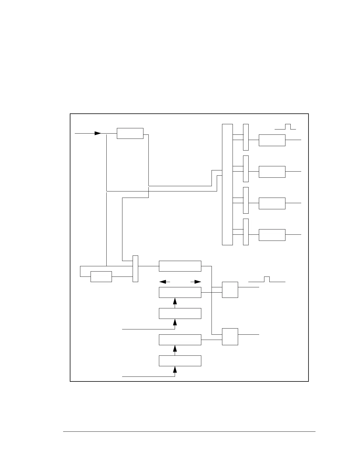
counter that can be read but not written. There are two 10-bit match registers and compar-
ators. If the match register matches the counter, a pulse is output. Thus the timer can be
programmed to output a pulse at a predetermined count in the future. This pulse can be
used to clock the timer-synchronized parallel-port output registers as well as cause an
interrupt. Timer B is convenient for creating an event at a precise time in the future under
program control.
Figure 2-3 illustrates the Rabbit timers.
Figure 2-3. Rabbit Timers
A1
perclk/2
A4
A5
A6
A7
Timer A System
10-bit counter
match reg
match reg
compare
Timer B System
next match
next match
10 bits
Timer_B1
Timer_B2
f/8