14
1145094-W2-D
Rada V12 Exposed Shower Valve
Rear Entry Supplies (rising or falling concealed pipework)
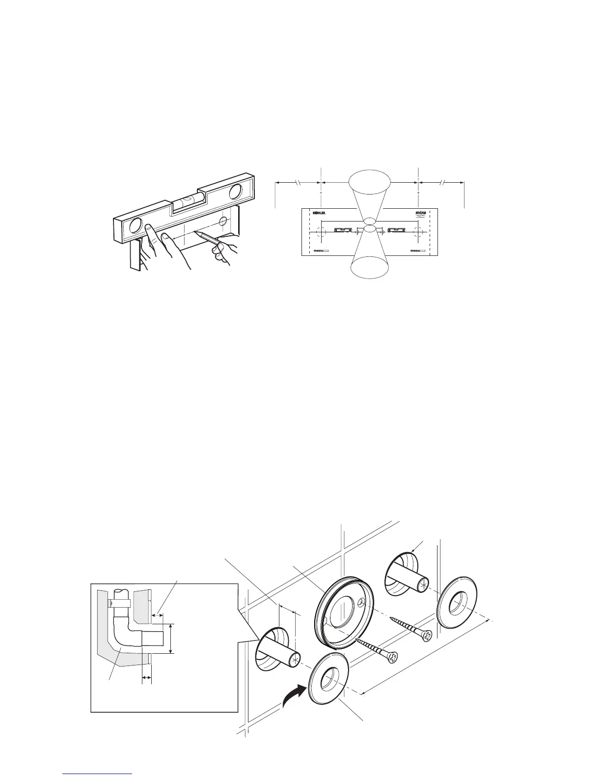
1. Use the Installation Template to mark the positions of the holes for the backplate
and the pipe centres (Not applicable for the V12 130 Centres Model).
Note! Allow a minimum of 150 mm either side of the mixer, to allow access to
the hot and cold Inlet lters for servicing.
40 mm
153 mm
Shower Control
Backplate Fixing Points
(Ø6 mm)
Bend tabs inwards
Use as a support for the spirit level
Bend tabs inwards
Use as a support for the spirit level
Hot Supply Inlet
(Ø15 mm)
Make sure that supply pipes are thoroughly flushed through
before connection to the shower control
Cold Supply Inlet
(Ø15 mm)
153 mm
150 mm
40 mm
150 mm
Ø32 mm x 10 mm depth
for Concealing Plates
153 mm
Apply Silicone
Sealant
Backplate
Concealing Plates
10 mm minimum
between Elbow
and nished wall
surface
32 mm
18 mm from
nished wall
surface
Elbow
2. For solid walls drill the holes for the backplate with a 6 mm drill and insert the
wall plugs (supplied). For other types of wall structure alternative xings may
be required (not supplied).
3. Drill the holes for the supply pipes at 153 mm centres.
4. Recess the wall to allow for the pipe concealing plates, Ø 32 mm x 10 mm
deep.
Note! Depth must be sufcient to prevent the concealing plates fouling on the
plumbing elbows.
5. Fit the supply pipework (Hot - Left, Cold - Right). The pipework must project
18 mm from the nished wall surface at 153 mm centres (use the Installation
Template as a guide).
Note! If the connections are reversed, then turn the valve through 180° to
ensure that the hot supply is connected to the hot inlet and reverse the outlet
fittings as necessary, refer to section: ‘Reversed Inlet Supplies’
Hot
Cold