— 6 —
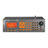
DC Voltmeter
Set
PTT
MIC
JACK
ANT
J501
J751
Dummy Load
(50-ohm)
And Attenuator
ALIGNMENT AND ADJUSTMENT
ALIGNMENT OF PLL
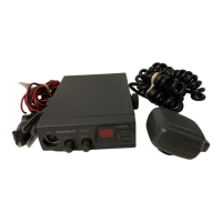
Test Equipment Required and Connections
• DC power supply: 13.8 V • DC voltmeter • Dummy load (50-ohm)
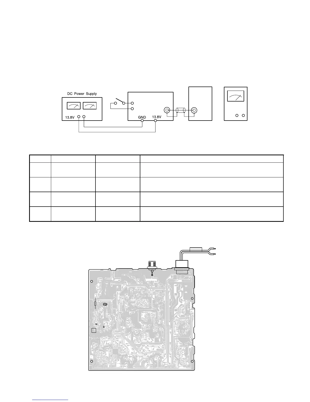
Alignment Point Locations (Main PCB)
Alignment Procedure
Step Preset to Adjustment Remarks
1 TX 40 CH L301 Adjust L301 to obtain 3.8 ±0.1 V (DC) at TP3 (R304).
2 TX/RX 1 ~ 40 CH —
Check if the DC Voltage on all channels is kept within
1.5 V to 3.9 V at TP3.
3 RX 40 CH CT301 Adjust CT 301 to obtain 16.71 MHz ±50 Hz at TP7 (R216).
4 WX 1 ~ 7 CH —
Check if the DC Voltage on all channels is kept within
1.0 V to 4.0 V at TP4.
DC CORD
FUSE
ANT
J501
TP7
R216
TP3
R304
L301
TP4
R325
CT301
J502
WA901
GND(BLK)
13.8v(RED)

 Loading...