— 7 —
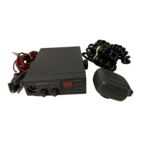
DC CORD
ANT
J501
L205
RT201
J502
Microphone jack J751
WA901
GND(BLK)
13.8v(RED)
FUSE
Transceiver
AF Oscillator
PTT
MIC
Jack
ANT
Jack
J501
J751
Dummy Load
(50-ohm)
And Attenuator
RF Power Meter Modulation Meter
5
4
10 F
16V
+
ALIGNMENT OF TRANSMITTER SECTION
Test Equipment Required and Connections
• DC power supply: 13.8 V • Modulation meter • AF oscillator
• RF power meter • Dummy load (50-ohm) & attenuator
Preset
• ALERT/WX/CB position: CB
Alignment Procedure
Alignment Point Locations (Main PCB)
Step Preset to Adjustment Remarks
1
No modulation
19 CH
L205
Adjust L205 by turning the core clockwise to obtain 3.8 W
reading on the RF power meter.
2 No modulation — Confirm frequencies of all channels are within specification.
3 No modulation RT201
Adjust RT201 to position the indicator in the meter MT501
just on "SIG9".

 Loading...