— 8 —
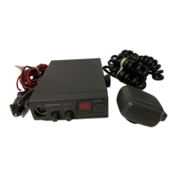
Transceiver
ANT
Jack
J501
EXT.
SP.
J3
AC Voltmeter
SINAD Meter
Dummy Load
(8-ohm)
Distortion Meter
Signal Generator
ALIGNMENT OF RECEIVER SECTION
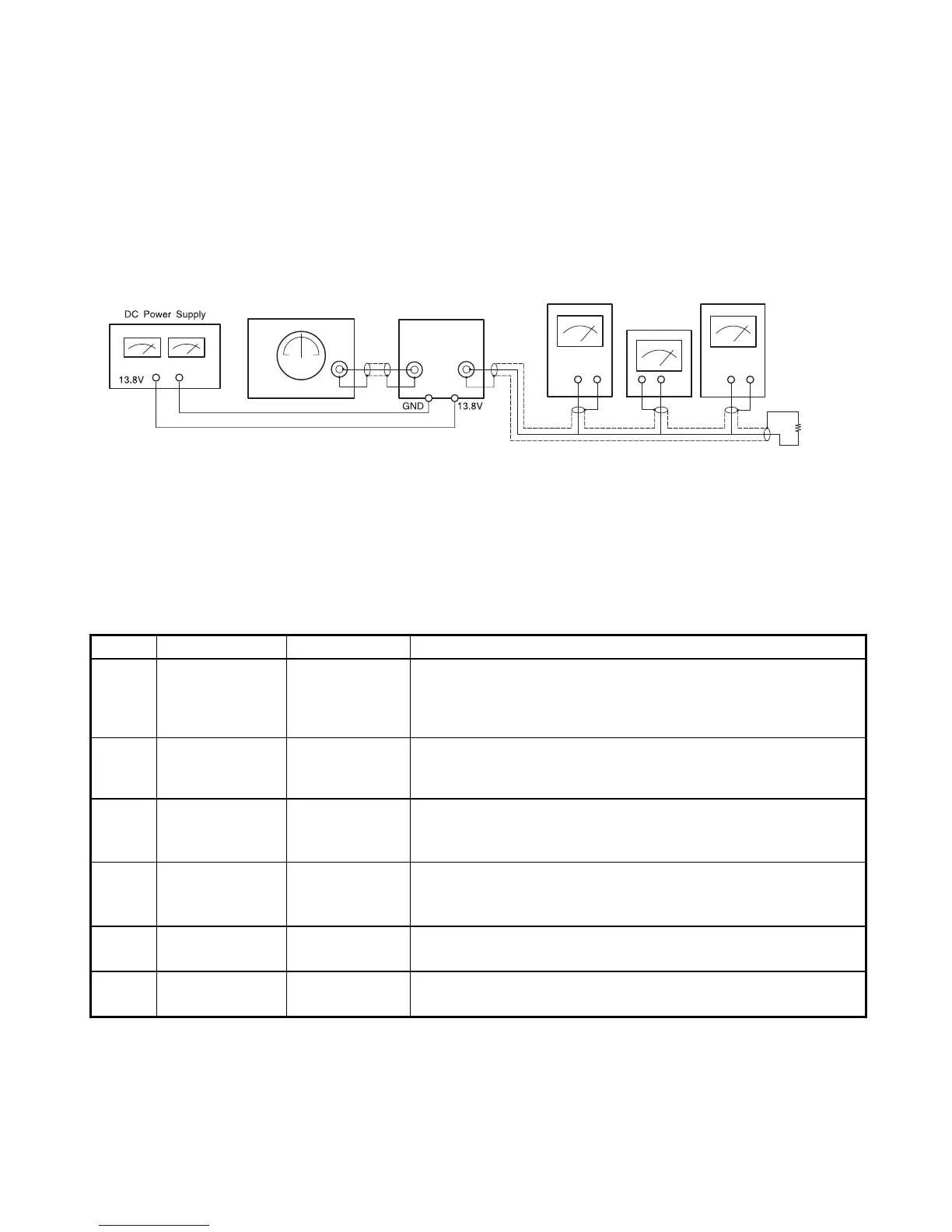
Test Equipment Required and Connections
• DC power supply: 13.8 V • AC voltmeter • Dummy load (8-ohm, 5 W resistive)
• Signal generator (SG) (27.205 MHz, 1 kHz, 30% AM modulation, output inpedance 50-ohm): CB
(162.45 MHz, 1 kHz, ±3kHz Dev. FM modulation, output impedance 50-ohm): WX
• SINAD Meter • Distortion meter
Preset
• ALERT/WX/CB: CB
Alignment Procedure
Step Preset to Adjustment Remarks
1
Vol.: Max.
SQ.: Min.
RX: 20 CH
L3, L1, L7, L5
L6, L2
Connect the SG to the antenna jack (J501) and the AC voltmeter
across the dummy load (8-ohm) to the external speaker jack (J3).
Adjust coil (L1 ~ L7) to obtain the maximum reading on the AC
voltmeter with keeping the level of the SG.
2
Vol.: Standard
SQ.: Min.
RX: 20 CH
L4
Set the output level of SG to 1 mV (−47 dBm).
Adjust coil L4 to obtain minimum Reading on the Distortion
Meter.
3
Vol.: Standard
20 CH
SQ.: Max.
RT1
Set the output level of SG to 1 mV (−47 dBm).
Adjust RT1 so SQ just opens.
4
Vol.: Standard
SQ.: Min.
RX: 20 CH
RT2
Set the output level of SG to 100 µV (−67 dBm).
Adjust RT2 to position the indicator in the meter MT501 just on
"SIG9".
5 WX: 3 CH L103
Set the output level of SG to 100 µV (−67 dBm) No modulation.
Adjust coil to obtain the maximum reading on the AC voltmeter.
6 WX: 3 CH RT101
Set the output level of SG to SINAD 15 dB.
Adjust RT101 so SQ just opens.

 Loading...