RD4000 Locating System User Manual
Page 43
RD4000MRx OPTION
The RD4000M option enables users to locate all Electronic Marker System (EMS) and Omni
TM
markers. Folding
down the special antenna activates the EMS function. In EMS mode, the receiver can be used to locate a buried
conductor and a marker simultaneously or locate markers independently. In dual mode, the left/right arrows
indicate the buried conductor position while the bargraph, numeric display, and audio response indicate the
amplitude of the received marker signal.
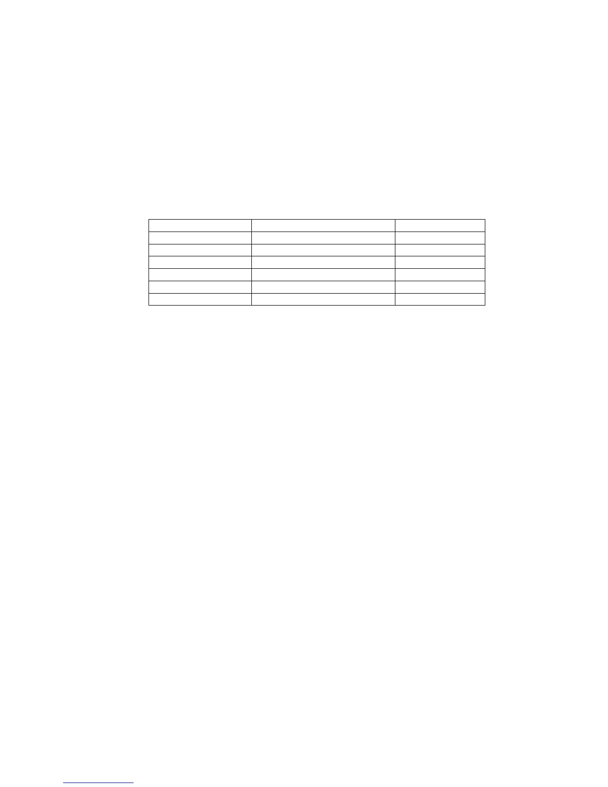
The full range of markers, as listed below, can be located without the need to change to a different antenna.
EMS markers are available in six frequencies and six different industry colours for all utility applications.
Application Colour Frequency
Power Red 169.8 kHz
Water Blue 145.7k Hz
Sanitary Green 122.5 kHz
Telephone Orange 101.4 kHz
Gas Yellow 83.0 kHz
Cable TV Orange/Black 77.0 kHz
The RD4000M option is compatible with 3M™ and ScotchMark™ EMS markers, Omni™ markers, pegs, or any
other electronic marker tuned to the accepted frequency.
Selecting EMS mode
• Press the on/off key to switch the receiver on
• Fold down the EMS antenna. The receiver will enter display mode and display the last type of marker that
was selected.
Changing EMS marker type
• Press the frequency key to select the marker you wish to locate. The abbreviations for each type of marker
are displayed as:
PWR (Power)
H20 (Water)
SAN (Sanitary)
TEL (Telephone)
GAS (Gas)
CTV (Cable television)
Locating EMS markers
Dual mode locating
Use this mode when locating the marker and conductor simultaneously. To locate the conductor the transmitter
applies a signal to the cable. In EMS marker mode the receiver has two gain levels, (high and low) indicated at
the top left of the display. The high and low levels are selected using the gain paddle (clockwise for high,
anticlockwise for low). The default sensitivity is high. The buried conductor signal gain is controlled automatically
in this mode and is automatically set to null locate using the left/.