RD4000 Locating System User Manual
Page 40
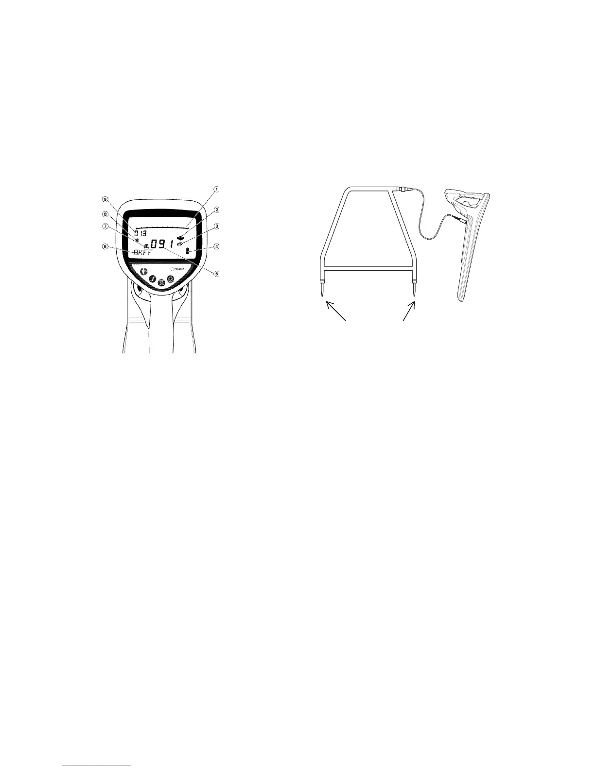
Connecting the A-frame to the receiver
• Plug one end of the connection lead into the A-frame socket
• Plug the other end into the receiver accessory socket
• Switch the receiver on by pressing the on/off key.
The receiver will automatically recognise that an A-frame has been connected and the FaultFind screen will be
displayed (see illustration).
Receiver FF display A-frame connected to the RD4000 receiver
(1) Bargraph (disabled in FF)
(2) Fault direction indication arrow
(3) Measurement units
(4) Battery level indicator
(5) FaultFind signal strength
(6) FaultFind frequency
(7) A-frame connected indicator
(8) Volume level
(9) Locate signal gain level.
Note: Both the bargraph and audio output are disabled during FF.
green red