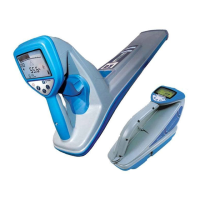
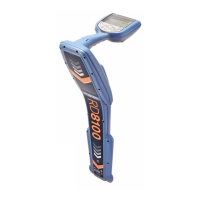
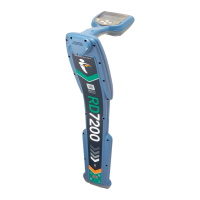
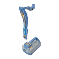
RD4000 Locating System User Manual
Page 51
Selecting a power output level
• Select the required frequency.
• Press the up arrow key to select a higher output level and press the down arrow to select a lower output
level. The power output indicator will display a visual indication of achieved output level.
Output levels for each segment of the indicator are shown in the following table:
NUMBER OF
SEGMENTS
Direct -
Locate
Direct - ACID Direct -
FaultFind
Induction + All
Others
Outline 10mA
1 bar 30mA 30mA (25%)
2 bar 60mA
3 bar 100mA 100mA Normal
(50%)
(50%)
4 bar 200mA
5 bar 400mA 400mA (75%)
6 bar 700mA
7 bar 1A 1A Boost
(100%)
(100%)
Note: If the transmitter is outputting less than 10mA the display flashes “10mA” to indicate that better
connections are required.
Selecting induction
Ensure that there is not an accessory plugged into the transmitter. Switch the transmitter on. Induction mode is
automatically selected and the induction mode symbol is displayed. There can be two induction frequencies
available in the RD4000T10. Use the frequency key to select the induction frequency required.
Using the VΩ function
In locate mode the line output voltage can be measured by pressing and holding down the VΩ key.
In measure mode DC resistance on the line can be measured by pressing and holding down the VΩ key.
Measure mode can be used for frequencies up to dc 200KHz on lines up to 30V (SELV) only.
To access measure mode and take a resistance reading:
• Press on/off to select the menu and scroll using the down arrow to select Measure.
• Press on/off again to confirm selection.
• Press and hold down the measurement key to select ohms and take a resistance reading.
Selecting FF mode
• Switch the transmitter on
• Ensure the direct connection leads are plugged in
• Press the menu key and press the up or down arrow until ‘FaultFind’ is displayed.

 Loading...

