CONTENTS
1. INTENDED USE ................................................................................................................................................. 5
2. WARRANTY CONDITIONS ............................................................................................................................... 5
3. MAINTENANCE ACTIVITIES ............................................................................................................................ 6
3.1. Cleaning Stainless Steel Components ........................................................................................................ 6
3.2. Cleaning ABS Components ......................................................................................................................... 6
4. DESIGN .............................................................................................................................................................. 6
4.1. Dimensions .................................................................................................................................................. 6
4.2. Connectors Arrangement ............................................................................................................................ 7
4.3. Pins Arrangement ........................................................................................................................................ 7
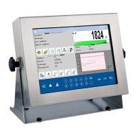
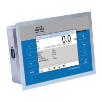
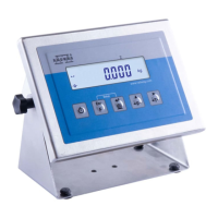
4.4. Operation panel ........................................................................................................................................... 8
4.5. Technical specifications............................................................................................................................... 9
5. INDICATOR INSTALLATION ............................................................................................................................ 9
5.1. Unpacking and Installation .......................................................................................................................... 9
5.2. Start-Up ..................................................................................................................................................... 10
5.3. Battery Charge Status ............................................................................................................................... 10
5.4. Battery Charge Status Check .................................................................................................................... 10
6. OPERATING THE MENU ................................................................................................................................. 11
6.1. Return to the Weighing Mode .................................................................................................................... 11
7. INSTALLER INSTRUCTION ............................................................................................................................ 11
7.1. Connecting 6-Wire Load Cell .................................................................................................................... 11
7.2. Connecting 4-Wire Load Cell .................................................................................................................... 12
7.3. Connecting Load Cell’s Cable Shield ........................................................................................................ 13
8. FACTORY SETUP ............................................................................................................................................ 14
8.1. Access ....................................................................................................................................................... 14
8.2. Factory Parameters List ............................................................................................................................ 15
8.3. Device Defining ......................................................................................................................................... 17
8.4. Factory Adjustment .................................................................................................................................... 18
8.4.1. External Adjustment Process ......................................................................................................... 18
8.4.2. Start Mass Determination ............................................................................................................... 18
8.4.3. Correction of Start Mass Expressed in Converter's Divisions ....................................................... 19
8.5. Linearity Correction ................................................................................................................................... 19
8.5.1. Entering Linearity Correction Points ............................................................................................... 19
8.5.2. Corrections ..................................................................................................................................... 20
8.5.3. Deleting Linearity ............................................................................................................................ 20
8.6. Gravitational Coefficient ............................................................................................................................ 20
9. OPTIONAL EXTENSION MODULES .............................................................................................................. 21
9.1. Input/Output Module .................................................................................................................................. 21
9.1.1. Technical Specifications ................................................................................................................. 21
9.1.2. I/O Schematic Diagrams ................................................................................................................ 22
9.1.3. Input / Output Signals Overview ..................................................................................................... 22
9.2. 4-20mA Module ......................................................................................................................................... 23
9.2.1. Technical Specifications ................................................................................................................. 23
9.2.2. Wiring Diagrams of 4-20mA Module .............................................................................................. 24
9.3. RS485 Module ........................................................................................................................................... 24
9.3.1. RS485 signals description .............................................................................................................. 24
9.4. Ethernet Module ........................................................................................................................................ 25
9.4.1. Ethernet Pins .................................................................................................................................. 25
9.5. Additional Modules Arrangement .............................................................................................................. 25
10. DIAGRAMS OF CONNECTION CABLES ..................................................................................................... 26
 Loading...