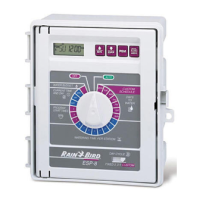
9
Power Wiring Connections
120 VAC (US)
230 VAC
(International)
Black supply wire (hot)
to the black transformer
wire
Black supply wire (hot)
to the black transformer
wire
White supply wire
(neutral) to the white
transformer wire
Blue supply wire (neutral)
to the blue transformer
wire
Green supply wire
(ground) to the green
transformer wire
Green-with-yellow-stripe
supply wire (ground) to
the green-with-yellow-
stripe transformer wire
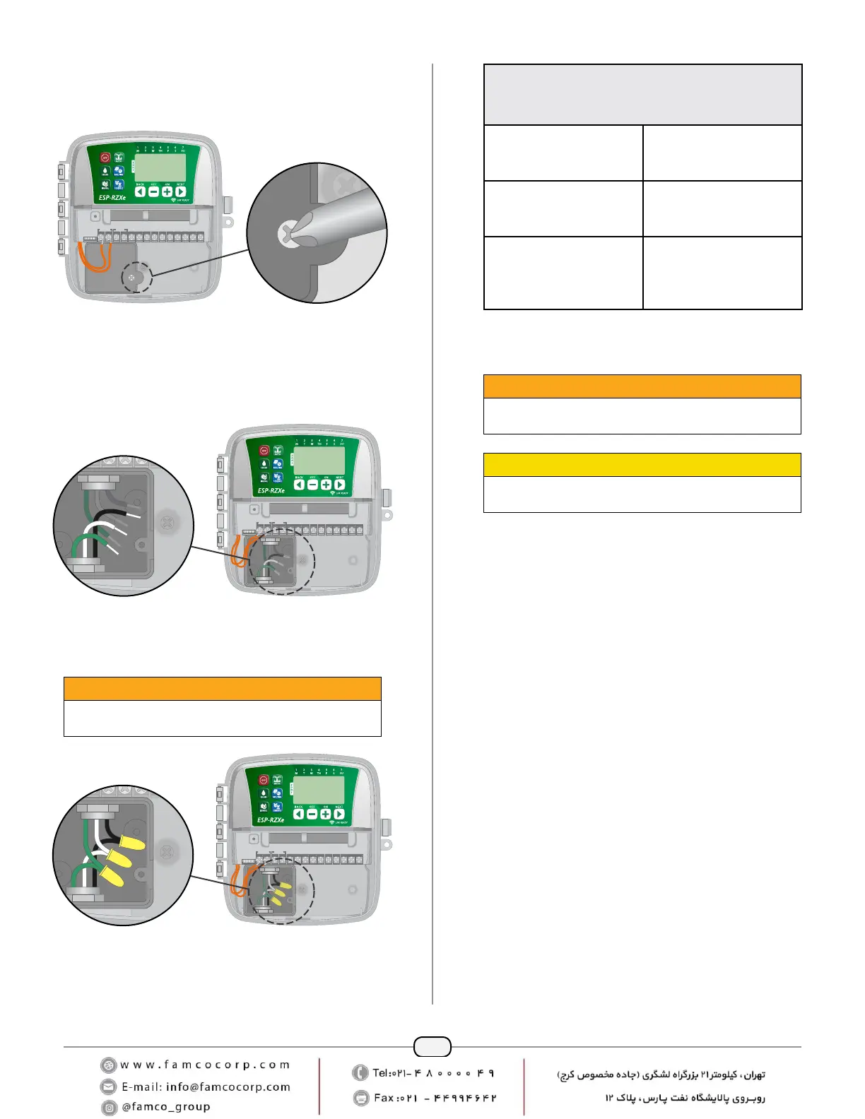
Verify that all wiring connections are secure, then
replace the wiring compartment cover and secure it
with the screw.
WARNING
DO NOT turn on power until you have completed and
checked all wiring connections.
CAUTION
DO NOT use an outlet that is controlled by a secondary
ON/OFF light switch or GFI outlet.
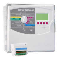
Locate the transformer wiring compartment in the
lower left corner of the controller unit. Use a screw-
driver to remove the cover and expose the trans-
former connection wires.
CONNECT
120 VAC
REMOTE
24VAC
ACCESSORY
SENS
12345678CM
RESET
Route the three external power source wires through
the conduit opening at the bottom of the unit and
into the wiring compartment.
NOTE: If necessary, remove the knock-out on the
bottom of the controller below the transformer and
attach a 1/2 inch conduit to the unit.
REMOTE
24VAC
ACCESSORY
SENS
12345678CM
RESET
Using the provided wire nuts, connect the external
power source wires (two power and one ground) to
the transformer connection wires inside the wiring
compartment.
WARNING
Ground wire must be connected to provide electrical
surge protection.
REMOTE
24VAC
ACCESSORY
SENS
12345678CM
RESET
 Loading...