EasyManua.ls Logo

Rain Bird Image Series User Manual

Rain Bird Image Series
4 pages
To Next Page IconTo Next Page
Page #1 background imageLoading...
Page #1 background image
INDOOR
W
ALL
MOUNT
40
m
m
1
2
6
5
Ø
m 4 m
Ø 4 m
m
ø 4
m m
43
Image
L c
c
r e
r
o
ate the ont
oll
r nea a 230
V e
r
ur
,
50 H
z
pow
s
o ce. T
h
e
c
b
c
ontroller
must e
onnected to an
ele
ct
ri
cal i
n
st
a
lla
t
io
n h
at
t
co
o
r
ms
to
st
an
d
a
r s a
n
d is
n
f d
p
r
o
t t
by a
fuse i
n t
h
e
c
ed
e
e ectrical pa el
l
n .
Wir t t
e c
tr
v
vei
ng
o
he
l
e i
c a
l s
t
- l
e t
i
n
a c
t
1
I B
D
a v
p r s a
t
o
n
l s
ma
st
e a v
o
Mul
i v
a v
s
t
a o c
p
a i y
:
R
A
N IR
v
l
e e
t
i
p
u
a r
v
l
e r
p
s rt
r ay
ak
u
e
al
ir
e
f
r the c
t
r l
to
t
al
e
s
s odpum
t
a el
. M e
s
r l w
o
m
on o
l er
he
v v i
c
e
-
a r v d
r
un
e
rg
ro
d o g
e s .
pp
o
e
f
o d un
l w
v
ol
t
a
u e
e
l t
th
e s
ita
e
wir e ll o
n
n
ti
to
the
v v
eads nd
any
r
S
ec
u
b
l e
siz
.
A c
ec ons al e l
a w
i
e
pl
i
e
s i
d
mus
e
rti
.s
c
n
th
e
fi
el
t be
wa
t gh
t
Us
e R
ai
n
B
ir
d
Q
ui
c
C
on
ne
ct co
nn ct
ors :
k e
DBY,
DBR, DBM,
K
I
N
G
.
S
w
r
i
d ag
.
ee
i ng
i
ra
ms
A
= V
A
L
V
E
OX
B
B
P
R
A
=
UM
P S
T
AR
T E
L Y
C
POW
E
R
R
EL Y
=
A
D
=
PUM
P
E
ER S
U
L
O
D
= P
O
W
P
P
Y M
U
LE
0
0 4
P
1
0
F
= M
VAL E
AST
E
R
V
ir
i s
am c
on u
it
W
e
n e d
W
i
re
in
d
sam
e
con
uit
W
i
e
nr
i
d
s
a
me
c
on u
i
t
A
A
A
E
E
7
P10004
V
230
24 V
V
C P
1
2
3 4
24
Ø
3
mm
Ø 3 m m
LED
0
= 23
V
= 230V

Other manuals for Rain Bird Image Series

Question and Answer IconNeed help?

Do you have a question about the Rain Bird Image Series and is the answer not in the manual?

Rain Bird Image Series Specifications

General IconGeneral
MountingIndoor/Outdoor
Start Times per Program4
Cycle + SoakYes
DisplayLCD
Enclosure RatingNEMA 3R
Backup BatteryYes
Watering DaysCustomizable

Summary

Controller Installation and Wiring

Installation Requirements

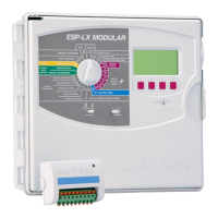
Locate controller near 230V, 50Hz power source, adhering to electrical standards.

Wiring to Electric Valves

Connect electric valves, use watertight splices and code-approved wire for underground use.

Wiring Options and Glossary

Pump Start Relay and Rain Check

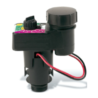
Wiring diagrams for pump start relays and the RAIN CHECK™ option.

LPVK-12E Wiring Diagram

Specific wiring configuration for the LPVK-12E controller option.

Irrigation Terminology

Definitions for controller, station, cycle, start time, and watering programs.

Controller Programming Guide

Programming Interface and Navigation

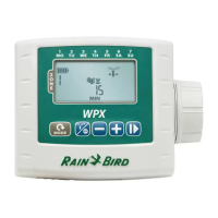
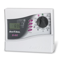
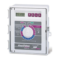
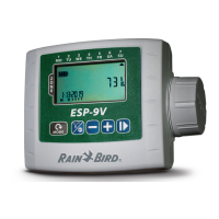
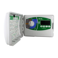
Understanding the circular menu, icons, and button functions for programming.

Setting Date and Time

Configuring the current time of day and the current day of the week.

Defining Watering Days

Selecting specific days of the week for watering programs A and B.

Advanced Programming and System Management

Watering Schedule Configuration

Setting multiple start times, station run times, and adjusting Water Budget.

Manual Operation and Shutdown

Initiating manual station/cycle starts and managing system On/Shutdown states.

Power Loss and Compliance Notes

Procedures after power outage and declaration of conformity to European directives.
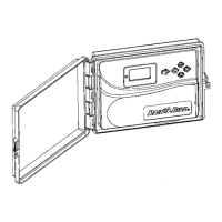
Related product manuals