Do you have a question about the Rancilio Silvia PID Kit and is the answer not in the manual?
Review terms, conditions, and warranty limitations before installation.
Detailed list of all components included in the PID kit for Watlow 96.
Essential tools needed to perform the Silvia PID kit installation safely.
Safely disconnect power and prepare the espresso machine for disassembly.
Steps to remove the water reservoir and front splash panel for access.
Securely install the Solid State Relay (SSR) onto the machine's chassis.
Detach the top panel, also known as the cup warmer, from the machine.
Review safety and disassemble the rear U-shaped enclosure panel.
Detach the internal splash guard to access internal components.
Carefully disconnect the electrical connectors from the brew thermostat.
Connect the new red power leads to the Solid State Relay (SSR).
Connect the control wires to the low voltage DC side of the SSR.
Fit the clear plastic cover over the SSR for electrical safety.
Install wire splitters onto the main power switch terminals.
Connect the power supply wires to the installed splitters.
Mount the thermocouple onto the boiler for temperature sensing.
Connect the new grounding wire to the machine's chassis.
Route all new wires through the machine's base using rubber grommets.
Decide whether to mount the controller enclosure on the left or right side.
Pass wires through the grommet in the enclosure's bottom cover.
Slide wires through the controller's locking collar before enclosure mounting.
Connect the ground wire to the designated tab at the back of the enclosure.
Connect the various wires to the correct terminals on the digital controller.
Securely insert the wired controller into its enclosure.
Secure wires with a clamp and attach the top and bottom enclosure covers.
Instructions for releasing or adjusting the controller's locking collar.
Attach the controller enclosure assembly to the side of the espresso machine.
Organize and secure excess wiring within the pump compartment.
Reattach the splash panel, rear panel, and top panel after wiring.
Fasten the main cable loom to the L-bracket for strain relief.
Adjusting the target temperature for the boiler using controller buttons.
How the controller behaves in steam mode without the steam control package.
Utilizing the controller for steam temperature management with the package.
Mount and connect the relay for the steam control package.
Detach the front cover to access the machine's steam switch.
Connect the brown wire from the relay to the hot terminal of the steam switch.
Connect the purple wire from the relay to the neutral terminal of the steam switch.
Connect the red "cap" wire from the relay to the steam switch's original wire.
Bypass the steam thermostat by installing a jumper wire.
Organize and secure wiring related to the steam control package installation.
Reassemble the machine's front cover after completing steam package wiring.
Instruction to return to specific steps in Part A after steam package installation.
| Type | PID Kit |
|---|---|
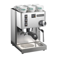
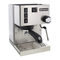
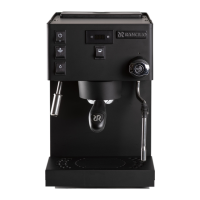
| Compatibility | Rancilio Silvia Espresso Machine |
| Function | Temperature Stability and Control |
| Temperature Control | PID Controlled |
| Display | Digital |
| Temperature Adjustment | Adjustable |
| Pre-infusion Capability | Yes |
| Installation | Requires Installation |
| Components Included | PID Controller, Wiring, Instructions |