Operating concepts
R&S
®
NRP Series
36Getting Started 1419.0170.02 ─ 16
– Mozilla Firefox 33 or later
– Google Chrome 36 or later
– Microsoft Internet Explorer 10 or later
– Safari 5.1 or later
Setup
3
1
2 4
6
HOST
INTERFACE
IN: 3 V or 5 V logic
OUT: min. 2 V into 50 Ω
max. 5.3 V
TRIG2
I/0
PoE
SMART SENSOR TECHNOLOGY
NRP
5
7
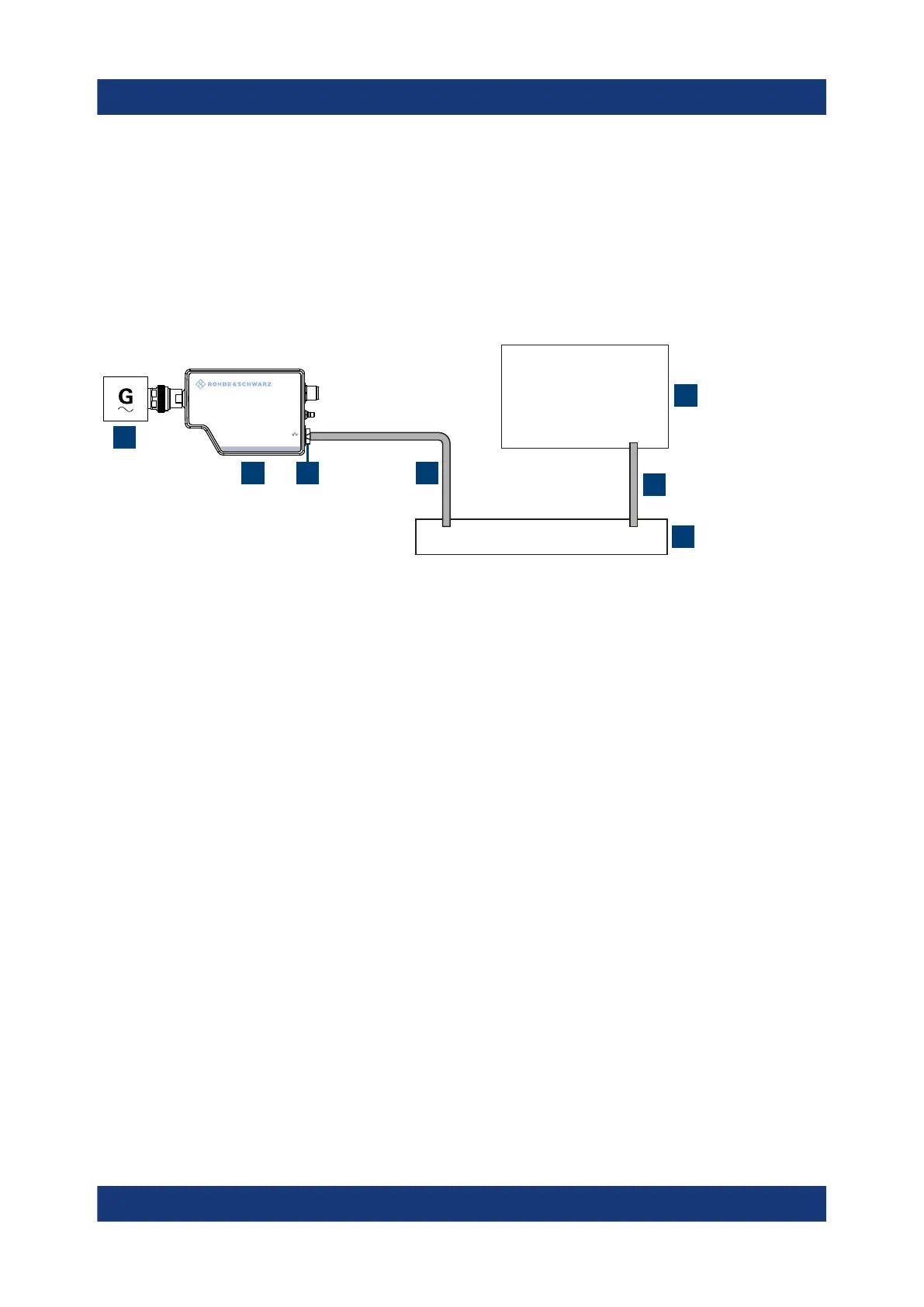
Figure 5-1: Setup with the web user interface
1 = Signal source
2 = LAN power sensor
3 = RJ-45 Ethernet connector
4, 6 = RJ-45 Ethernet cable
5 = Computer with a supported web browser installed
7 = Ethernet switch supporting PoE power delivery
1. NOTICE! Incorrectly connecting or disconnecting the power sensor can dam-
age the power sensor or lead to erroneous results. Ensure that you connect or
disconnect the power sensor as described in Chapter 3.4, "Connecting to a
DUT", on page 13.
Connect the power sensor to the signal source.
2. Connect the cables as shown in Figure 5-1.
For a detailed description, refer to Chapter 3.7.3, "Using a LAN connection",
on page 20.
Starting a measurement
1. Open a supported web browser.
2. Enter the instrument name or the IP address of the sensor you want to con-
nect to.
Example: http://nrp33sn-123456
Browser-based user interface

 Loading...

