Operating concepts
R&S
®
NRP Series
38Getting Started 1419.0170.02 ─ 16
The R&S NRPV is provided on your documentation CD-ROM and on the
Rohde & Schwarz website as a separate standalone installation package.
Required equipment
●
R&S NRP power sensor
●
R&S NRP‑ZKU cable or an R&S NRP‑Z5 sensor hub and an R&S NRP‑ZK6
cable to connect the sensor to the computer
●
Windows computer with installed:
– R&S NRP Toolkit V 4.20 or higher
– R&S NRPV version 3.2 or higher (refer to the operating manual of the
R&S NRPV for a description of the installation process)
Setup
1
2
3
4
5
6
NRP
3-Path Diode Power Sensor
MHz to GHz, 100 pW to 200 mW (−70 dBm to +23 dBm)
SMART SENSOR TECHNOLOGY
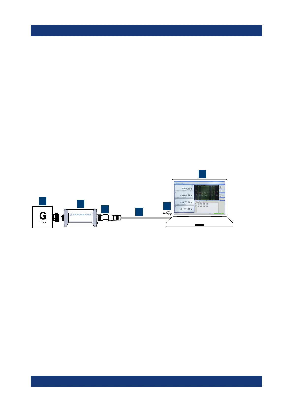
Figure 5-2: Setup with an R&S
NRPV
1 = Signal source
2 = R&S NRP power sensor
3 = Host interface connector
4 = R&S NRP‑ZKU cable
5 = USB connector
6 = Computer with installed R&S NRPV
1. NOTICE! Incorrectly connecting or disconnecting the power sensor can dam-
age the power sensor or lead to erroneous results. Ensure that you connect or
disconnect the power sensor as described in Chapter 3.4, "Connecting to a
DUT", on page 13.
Connect the power sensor to the signal source.
2. Connect the power sensor to the computer as shown in Figure 5-2.
For a detailed description, refer to Chapter 3.7.1.1, "Simple USB connection",
on page 16.
R&S NRPV

 Loading...

