INSTALLATION
Check the appliance is electrically safe when you have nished.
29
Final Fitting
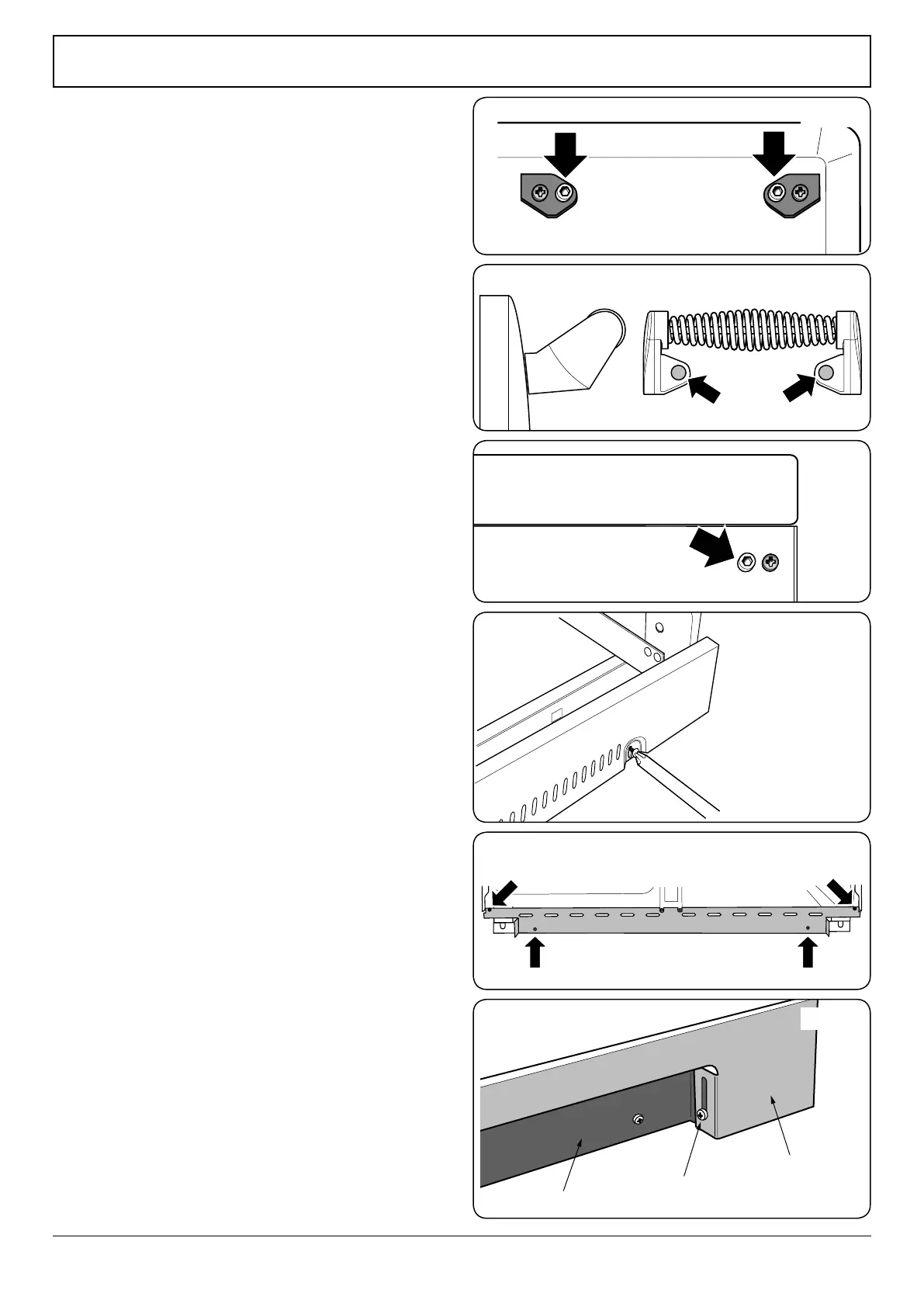
Fitting the Handles and Handrail (depending on
model)
Remove the 4 mm Allen screws from the doors (Fig.7-10). Fit
the door handles and secure using the 4 mm screws.
The handles should be above the xings.
Elan only: Fit the plastic blanking plugs to the xing holes
(Fig.7-11).
Remove the 4 mm Allen screws from the top corners of the
fascia (Fig.7-12). Fit the front handrail in position and secure
using the 4 mm screws.
Fitting the 1-piece Plinth
Loosen the three screws along the front bottom edge of the
cooker. Hook the central keyhole over the central screw. Twist
and t each end keyhole over their respective screws. Tighten
the xing screws (Fig.7-13).
Fitting the 2-piece Plinth (Classic Deluxe only)
Fit the inner plinth to the bottom front of the cooker using
the 4 screws provided (Fig.7-14).
Fit the outer plinth (2 screws, 1 each end) to the inner plinth.
The height of the outer plinth can be adjusted by sliding it up
or down via the slotted hole (Fig.7-15).
Fitting the Splashback (optional)
Position the splashback on the rear of the hotplate and secure
with the screws supplied.
Customer Care
Installer: Please complete your details in this Guide, inform
the user how to operate the cooker and hand oven the
instructions.
Thank you.
ArtNo.350-0012 - Securing the plinth
ArtNo.350-0010 - Fitting the plinth 1 (Kitchener)
ArtNo.350-0011 - Fitting the plinth 2 (Kitchener)
Outer plinth
Outer plinth xing screw
Inner plinth
ArtNo.215-0026 - Handle gaskets fixed
ArtNo.215-0027 - Elan handle blanking plugs
Art No 215-0028 - Handrail fascia fixings
Fig.7-10
Fig.7-12
Fig.7-11
Fig.7-13
Fig.7-14
Fig.7-15