34
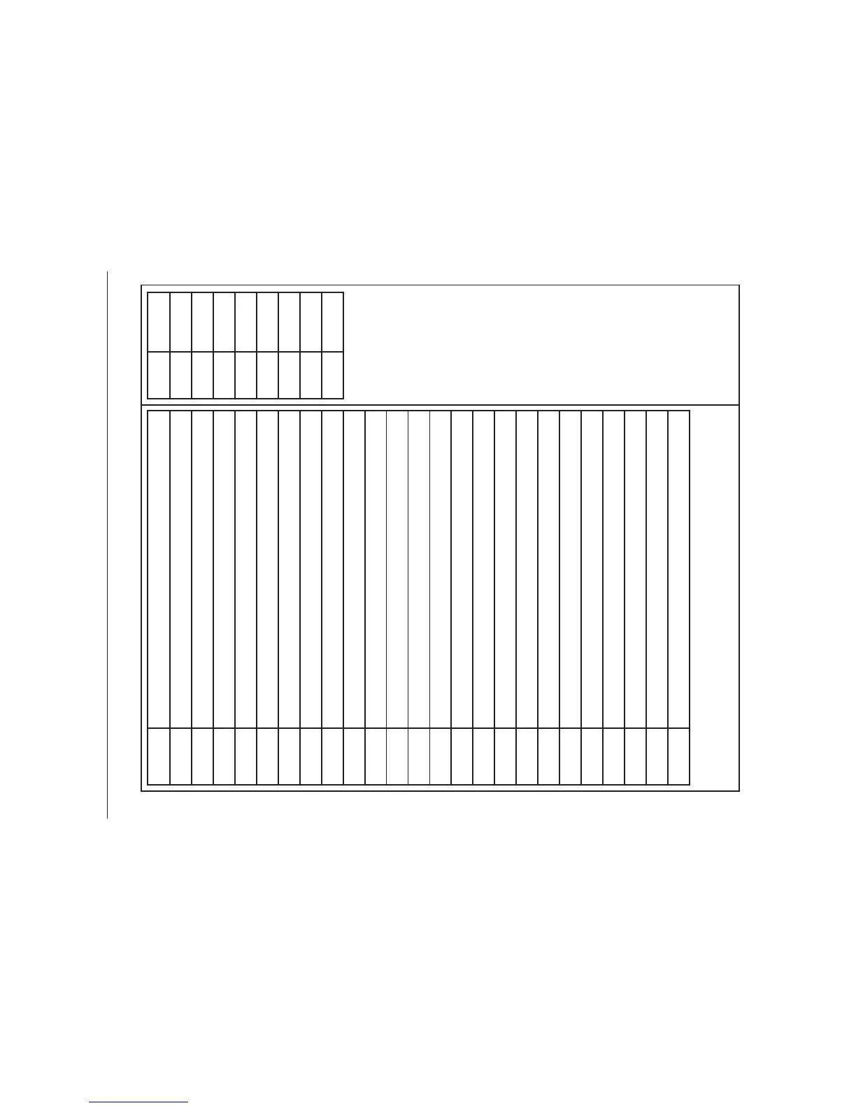
Circuit Diagram - Ovens
Connection shown in circuit diagram is for single phase. Ratings are for 230V 50Hz
Code Item
A1 Grill energy regulator
A2 Grill elements
A3 Grill Front switch
B1 Left hand Multi function oven thermostat
B2 Multi function oven function control
B2a Left hand Multi function oven thermostat frt.switch
B3 Multi function oven base element
B4 Multi function oven top element (outer pair)
B5 Multi function oven browning element (inner pair)
B6 Multi function oven fan element
B7 Multi function oven fan
D Clock
F1 Right hand oven thermostat
F2 Right hand oven switch block
F3 Right hand fan oven element
F4 Right hand oven fan
G1 Cooling Fan
H Oven light switch
I Oven light
J Cut-out
K Neon
M1 Slow cook oven thermostat
M2 Slow cook oven switch block
M3 Slow cook oven elements
Code Colour
b Blue
bl Black
br Brown
o Orange
r Red
v Violet
w White
y Yellow