STEERING SYSTEM INSTALLATION | CRX + SC1 | RAVEN EUROPE GENERIC
PAGE 17/36 | Installation manual | 016-8000-014EN | Rev. A1
Hint! :
In case the wheels of the tractor are steering,
when the hydraulics of the tractor are operated;
a non-return valve should be mounted in the
load sense line from the manifold. The non-
return valve should let oil pass from the
manifold to the check valve/pump and should
block in opposite direction.
Hint!:
A shuttle valve for CNH tractors can be provided
by Raven Europe (order no. 13348001014) or
the local CNH dealer (order no. 82018814).
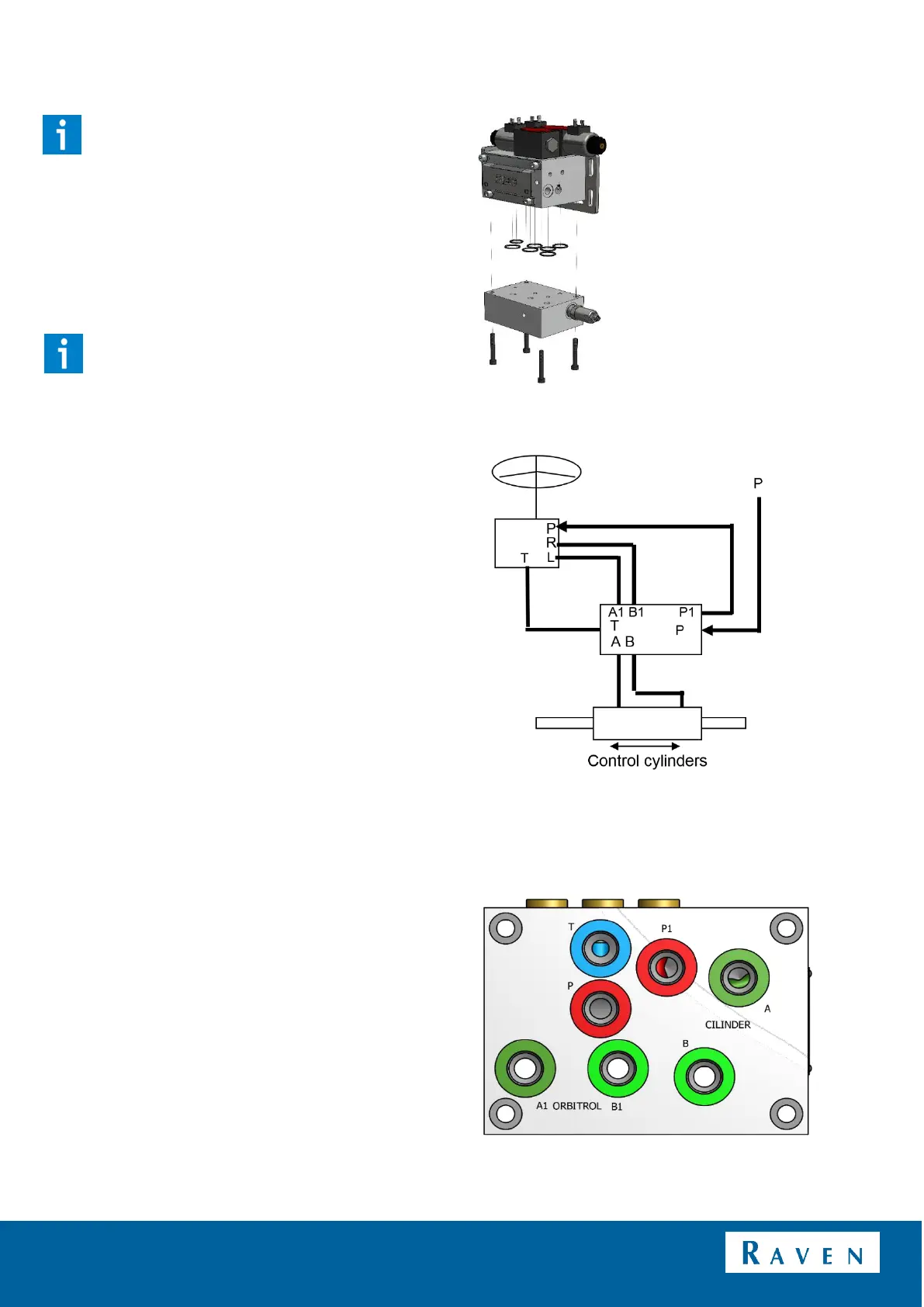
1.3.4 HYDRAULIC INSTALLATION OPEN CENTER
The manifold v3 open center consists of the standard
load sense manifold v3 with an add-on open center
part (Figure 9).
The pressure line that normally runs from the hydraulic
pump to the steering orbitrol, should be connected to
the P of the add-on open center part. Then connect a
line between P1 of the manifold and the pressure line
of the orbitrol. Connect the T of the manifold to a tank
inlet (Figure 10 and Figure 11).
Connect the hoses leading from the orbitrol to A1 and
B1 on the manifold. Connect the hoses to the steering
cylinders to A and B of the manifold (Figure 10 and
Figure 11).
FIGURE 9 ADD-ON PART OF THE OPEN CENTER
MANIFOLD
FIGURE 10 OPEN CENTER CONNECTION
CIRCUIT
FIGURE 11 CONNECTIONS OF THE HYDRAULIC
OPEN CENTER MANIFOLD
 Loading...