Wuhan Raycus Fiber Laser Technologies Co., Ltd.
User Guide of RFL- RFL-C1500X/C2000X
PIN 18, 20 of the DB25 control interface is applied to 24V (enable hardware
emission);
Send the start or stop emitting command (enable hardware emission) to control the
emission by Raycus software;
9) The laser is controlled by the user's "modulation" signal provided by the external MOD
interface
See 4.8 to get the process of laser shutting down.
4.7.4 AD mode
When PIN 20, 21 of the DB25 control interface is applied to 24V, the laser enters the
external AD mode, and the power of the laser is controlled by the voltage obtained by PIN 12,
13(1V-10% power, 10V-100% power).
When PIN 20, 21 is applied to 0V or left floating, the power of the laser is set by serial port
or Ethernet.
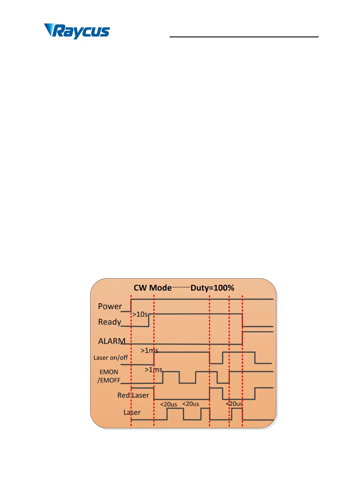
4.7.5 Control sequence diagram
Figure 10 Control sequence diagram of CW mode