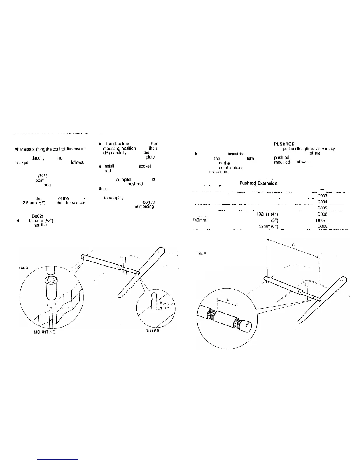
BASIC INSTALLATION
Alter
eslahlrshrng
Ihe
conlrol
dimensions
the Aulohelm 2000 can usually be
mounled
drreclly
onto
the
Starboard
cockprl seal (Fig 3). Proceed as
lollows.
TILLER PIN (Cal No. 0001)
l
Drill 6mm
(l/4”)
hole x 25mm (1”)
deep al
porn1
marked.
l
Using a Iwo parl epoxy adhesive such
as Araldile, bond the tiller pin into
place.
l
Position Ihe shoulder
01
Ihe pin
-
125mm
(r/z”)
above Ihe
liller
surlace.
MOUNTING SOCKET
(Ca! No. D602)
0 Drill 12.5nlrn
(l/2”)
hole x 25rnrn (1”)
deep
inlo
Ihe starboard cockpil seal.
II Ihe slruclure thickness al Ihe
mounling posilion is less Ihan 25mm
(1”) carelully reinforce Ihe under
surface wilh a plywood plale bonded
into position.
lnslall
the mounling
sockel
using Iwo
par1
epoxy adhesive.
Note The aulopilol is capable
01
generating high pushrod loads. Ensure
lhal:-
l
The epoxy is allowed to harden
Ihoroughly before applying any loads;
l
Ail holes are drilled to correcl size and
where necessary
reinlorcing
is
provrded.
MOI.INTING SOCKET
TILLEII
PIN
INSTALLATION
PUSHROD
EXTENSIONS (Fig.4)
ACCESSORIES
The
prrshrod
lengllr
IWI~
be
simply
II
il
is not possible lo
inslall
Ihe drive unil
directly onto Ihe cockpil seal or
tiller
as
described, one
01
the
lollowing
accessories (or combinalion) will ensure
a perfect inslallalion.
exlended using one
01
Ilre
slandard
pushrod
exlensions. Drrnension C
IS
modified
as
lollows:-
Dimension C
Pushrod
Extekion
Length L Cat No.
.
_
_
._
__
_
622mm (24.5”) Sld Dimension’
-
--.....-..
----.-..--.--
.-.. -.--- .
..--__-
__._
._..
_
--.-
-
._...
_~_
..__
.-.-
..-~-..-
-
646mm (25.5”) 25mm (1”)
0003
_ _
_
673mm (26.5”)
51 mm (2”) DO04
--_
^--....-........-
__
-....-.-
-
-...--...
..___...._...
-...-
_~-
____._...........
699mm (27.5”)
76mm (3”) DO05
_
.--. . .
_.
_.
_
-
.
.._._. ..-
.-
.___
__--_-...
--..
724mm (26.5”) 102mm
(4”)
0006
749rnrn
(29.5;;) --
127mm (5”)
Dcro7~-
775rnm (30.5”) 152mm
(6”)
DOOa.
.._
.- .
..__..._.
-..--
._
_.
--
~.._
._.._.......____..._
FICJ.
4