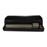
CONTROL UNIT
The conlrol unit slols into a permanently
mounled socket sited in the cockpit II
contains a gimballed fluxgale compass
and Iherefore has some
reslriclions
on
mounling posilion.
The control unit should be siled where
it
can be operated easily
horn
Ihe
steering positron. It should also be
posilioned al
leas1
60cm (2’6”) away
lrom
lhe
main steering compass lo avoid
devialion of both compasses.
Deviation of the control unit
fluxgale
compass is less imporlanl since
headings are always adjusted by
reference lo the main sleering compass.
Nevertheless, deviation should be
avoided if possible and thus the conlrol
unit should be siled as far away from
other
magnelic
or iron devices as
praclical.
Having selected the besl mounling
site, the mounling sockel may be
secured lo a convenient wooden or glass
libre surface using the self lapping
screws provided. The mounling surface
may slope away from verlical by a
maximum of 459
Battery Connection
The waterprool ‘Dri-Plug’ srrpplied
should be
silualetl
as close as possible lo
Ihe
Aulohelm 2000 lo minimise lead
length. The Dri-Plug sockel musl be
connecled
directly lo
the vessels
electrical dislribulion panel and on no
account paralleled into exisling wiring for
other equipment.
The Aulohelm supply must be
independently switched and
protecled
by a 5 amp fuse or current trip.
Since the autopilot is microprocessor
based
il
is very imporlant lhat vollage
losses in supply cables are minimised.
Supply cables sl~oulcl Iherelore he as
shorl as possible and
01
no less size
Win
sl~own
in
Ihe
lollowirg
lable.
The
brown
wire of the Autohelm 2000
lead should be connecled
lo positive.
II
connections are accidenlly reversed Ihe
Aulohelm 2000 will nol operate bul no
damage will result
Lead Length
Cop&r
Area
-.tJp
to 25m
(6’) 1 .Omm*
UP
P!vF!
(‘3’1
_
_
.__
__ !:?mmf..
-
-...
up
lo
65m
(22’) 2.5mm2
_
__ __ _--
..------.-
..------
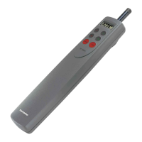
Accessory Connection
In common wilh all
Ihe
Aulohelm 2000’s
accessories, the drive unit plugs inlo Ihe
conlrol unit lo facilitate slowing and
servicing. To ensure reliable connection
each plug incorporates a locking ring
which should be turned clockwise lo
secure.
Although each accessory has a
unique socket and cannot be
misconnected,
Ihe drive unit should be
connected lo
Ihe
sockel marked
Helm,
Ihe
windvane
to Ihe socket marked Vane
and the hand held remole conlrol lo Ihe
sockel marked
Remote.