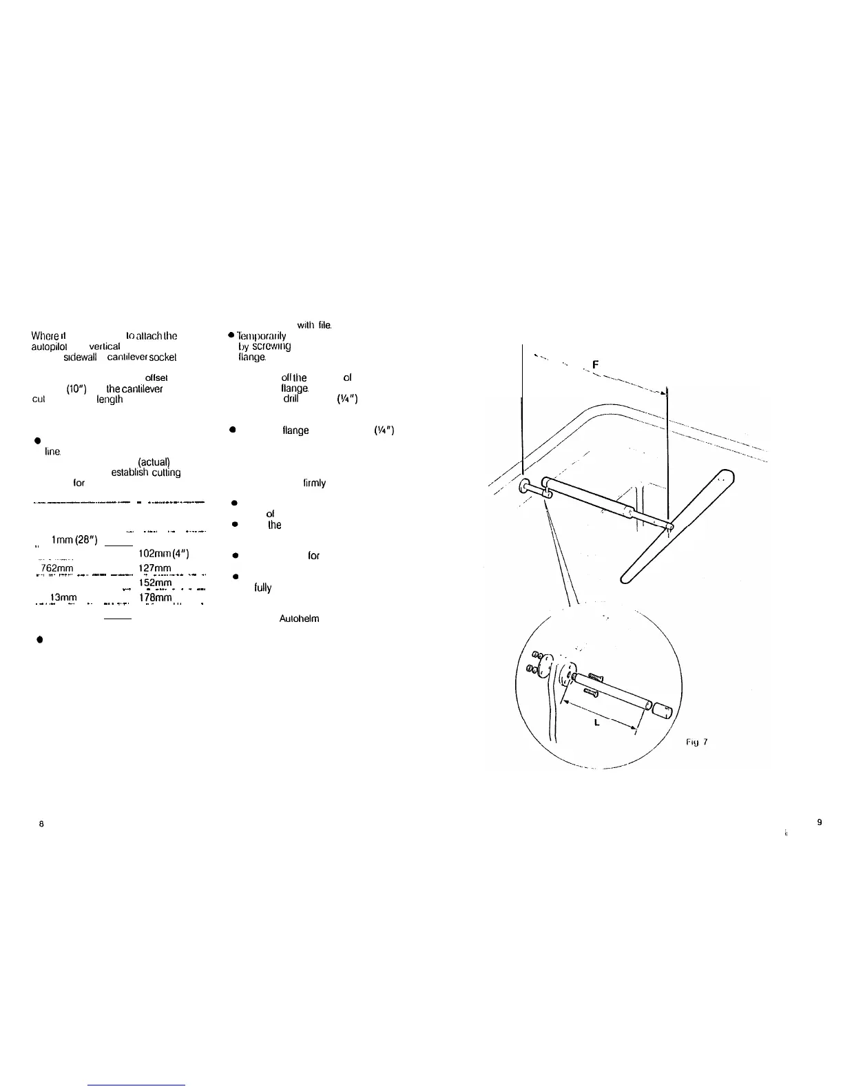
CANTILEVER MOUNTING (Fig.7)
Where
II
is ncccessary
lo
nllach Ihe
aulopilol
lo a
verlical
lace such as the
cockpit
srdewall
a
canlrlever
sockel
assembly is used.
The maximum exlension ollsel is
254mm
(10”)
and Ihe canlilever can be
GUI
IO the exact lenglh necessary during
mounting.
installation
0 Clamp the tiller on the yachl’s cenlre
line.
l
Measure dimension
F
(aclual)
l
Refer lo table lo eslablrsh
cutling
length lor cantilever rod.
_______._____
-
_.-.._-_-._-_--
Dimension F
Cut Length L
686mm (27”) I
51 mm (2”)
.__
.._..
._
_.._~
71
lmm(28”)
75mm (3”)
-.
737mm (29”)
102mrn
(4”)
762mm (30”) 127mm (5”)
_~.
._.
.-__.
_-.
.-.-.
---..
.-
-----..---
.-
-.
787mm (3 1”)
152mm (6”)
_
-
_._.
_
_
_
--.
8 13mm (32”)
178mm (7”)
.-..-
_.
_~
-.. _-.
..-
. .
..-
---
-
838mm (33”) 203mm (8”)
0
Cut cantilever rod to length
L
using a
hacksaw.
Measure
from threaded end.
l
Remove burrs
with
He.
0
Tr?rriporarily
assemble the cantilever
by
scrcwrrlg
the rod into the mounting
Ilange.
l
Ensure lhe drive unit is
horizontal
and mark oil
Ihe
location
ol
the
mounting
Ilange.
l Mark and
drill
3 x 6mm
(V4”)
clearance holes (ignore the two inner
holes).
0 Mount the llange using 3 x 6mm
(l/4”)
diameter bolts wilh nuts and washers.
Be sure to install the backing plate
correctly. Bed the flange on a thin coal
of silicone sealant.
l
Screw the rod
lirmly
into place using a
tommy bar.
Roughen the end of the rod and the
inside
01
the cap to provide a key.
Apply
Ihe
two part epoxy adhesive
provided to the rod end and cap and
place the cap over the rod end.
Ensure the hole lor the drive unit
mounting pin is lacing up.
Allow the epoxy adhesive 30 minutes
to
lully
harden before applying any
load.
When the Autohelm is not in use the
complete rod assembly may be
unscrewed, leaving the cockpit
unobstructed.
_
-_.
.._
._
F
--..
---_
.--..
.-__
-,
9
;/