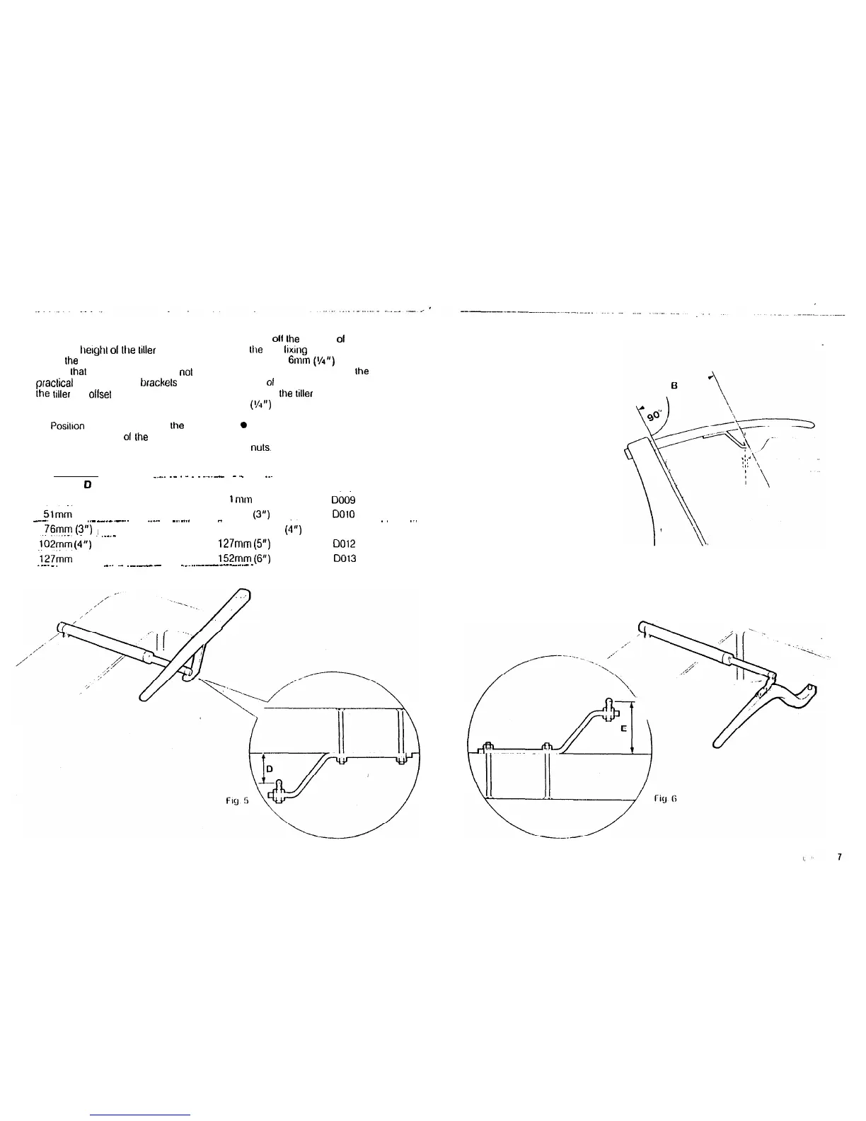
TILLER BRACKETS (Figs.5 and 6)
Where the
herghl
01
Ihe
loller
above or
below Ihe cockpil seat or mounting plane
is such lhal slandard mounling is
not
practicat a range of tiller brackels allows
the
loller
pin o&et lo be varied.
Installation
l
Posilron
the tiller bracket on Ihe cenlre
line (upper/lower)
01
the
tiller and
eslablish lhe control dimensions A
and B.
l
Mark
oil
Ihe position
01
the cenlres of
Ihe Iwo
Itxing
boll holes.
l
Drill Iwo 6mm
(Y4”)
diameler
clearance holes through Ihe cenlre
line
01
the Irtter.
l
Install Ihe
liller
bracket using 2 x 6mm
(I/J”) diameter bolls, nuts and
washers.
0
Bond lhe lixing bolls in place wilh
epoxy adhesive and fully lighlen the
nuts.
SLOPING TILLER
.._..
.-
_
.
.
.
-..-
-._
..~
Dimension
Cl
(below litter)
Dimension E (above litter)
25mm (1”)
5
1
nw1
(2”)
5tmm
(2”) 76mm (3”)
_-.
______ __
..-
_______.
___..
-..-...
.
-
76mm
(3”)
I
..-._
102mm (G)
102mm
(G)
Cat No.
0006
DO10
DO11
-.
..
127mm
(5”) 0012
.127mm (5”)
152mm
(6”)
DO13
._-._.
__
_..
~_
._.__
--. __~__.-------_-_
6