PEDESTAL SOCKET MOUNTING
II may be necessary lo raise the hcrghl ot
Ihe
Aulohelrn
mourrliny sock& above
Ihe
mounting surlace. For this a pedeslal
sockel assembly is used.
Selection
l
Lock Ihe lilter on the yacht’s cenlre
tine.
l
Establish the slandard control
dimensrons
A
and
B.
l
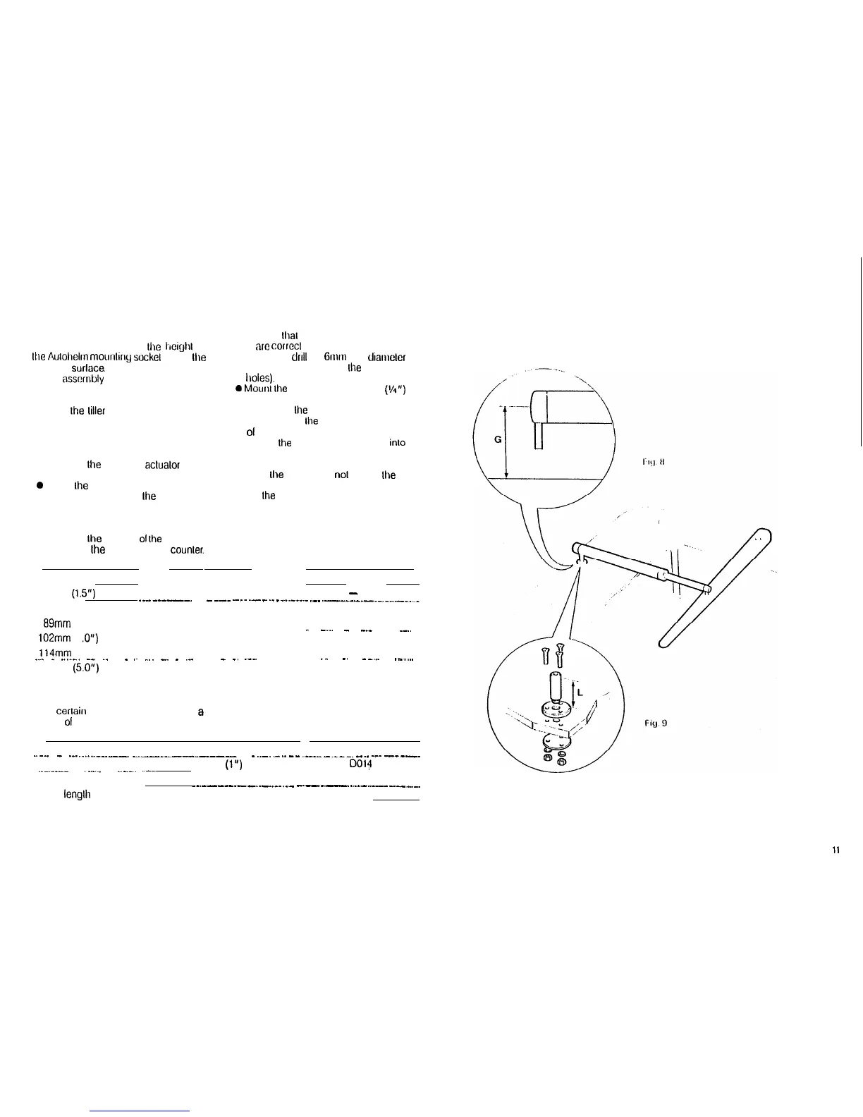
Measure dimension G (Fig.8)
ensuring Ihe Aulohetm aclualor is
horizontal.
0 Setecl lhe appropriale pedestal
socket assembly from
Ihe
table
shown.
Installation /
l Mark oft Ihe position
01
Ihe
mounling
llange on Ihe cockpil seal or
counler.
l
Ensure that control dimensrons A and
B
are
corrccl
l Mark and
drrtt
3 x 6mm (VI”)
dramcler
clearance holes (ignore Ihe Iwo inner
Iroles).
0 Mounl
Ihe
ltange using 3 x 6mm
(I/q”)
diameter bolls, nuls and washers,
being sure Ihe back ptale is installed
correclty. Bed Ihe ltange on a thin coat
01
silicone rubber sealanl (Frg.9.)
l Screw
Ihe
mounling socket lirmty inlo
place.
When
lhe
Aulohelm is nol in use
Ihe
mounling sockel may be unscrewed lo
leave
Ihe
cockpit unobslrucled.
Dimension G Pedestal Socket Length L Cat No.
38mm
(1.5”)
Std. Dimension
-
__-_---_-.
---
-
--_
--_.
._
_
._
_
__.-__-
.-- .________._.....___._
76mm (3.0”) 38mm (1.5”)
DO26
69mm (3.5”)
50mm (2.0”)
DO27
-
-....
-
-_-
.
--..
102mm
(4 .O”)
64mm (2.5”)
DO28
114mm (4.5”) 76mm (3.0”)
DO29 --
_...
-
_..._..
-__
._
.
_ .~
.._.
_.
_
.__
__
_
_.
._.. ._
-.
--_.
___....
127mm (5.0”)
89mm (3.5”)
DO30
TILLER PINS
For
cerlain
non-slandard inslattations e
range
01
litler pins is available.
Description
Sire
Cat No.
..--.
-
___......____
-_--_--------
. .
-
..-.
-
..--
.-___-._--.
__._
-_-
_____.
Small lhreaded titter pin
25mm (1”)
..-.----.-
DO14
._.-..
.._._..
..--.
Extra length tiller pin
72mm (2.8”)
DO20
-_.-----_-
._.__.__
-___
_.--__
____.
-..------
___._..
Extra lenglh lhreaded tiller pin
72mm (2.8”)
DO21
10
11