14 DSM300 and DSM30 Installation Manual
1.5 Cable Runs
Consider the following before installing the system cables:
• You will need to attach power, transducer, and display cables.
• All cables should be adequately secured, protected from physical damage,
and protected from exposure to heat.
• Avoid running cables through bilges or doorways, or close to moving or hot
objects.
• Avoid sharp bends.
• Use a watertight feed-through wherever a cable passes through an exposed
bulkhead or deckhead.
• Secure cables in place using tie-wraps or lacing twine. Coil any extra cable
and tie it out of the way.
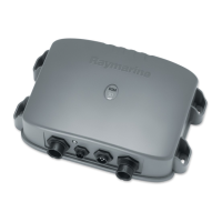
1.6 System Connections
The connector panel provides the following connection sockets:
•
T/D, 7-pin socket for connecting to the transducer
•
HSB2, 4-pin socket for connecting to a C Series or hsb
2
PLUS Series display
•
POWER, 3-pin socket; two for connecting to boat’s DC power and one RF
ground (screen) connection
•
SEATALK HS, RJ-45 socket for connecting to an E Series display
CAUTION:
To protect exposed pins, please place the attached dust cover
over the socket (4-pin or RJ-45) to which you are not connecting a
cable.
D7464-2
10.7 to 18 VDC (DSM30)
E Series Display
Transducer
C Series or hsb PLUS
2
10.7 to 32 VDC (DSM300),
 Loading...


