Do you have a question about the Raymarine DSM300 and is the answer not in the manual?
Equipment must be installed and operated per manual. Failure may result in injury or navigational inaccuracies.
Information correct at press time; specifications may change without prior notice.
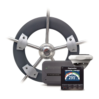
Describes operating the DSM300 with hsb² PLUS displays and its sonar capabilities.
Guides users through the handbook's chapters and content structure.
Provides basic instructions for using DSM300 with PLUS displays and covers Simulator mode.
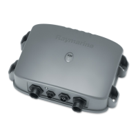
Explains how the unit powers on and the importance of accessible power cord.
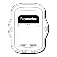
Describes the LED indicator on the front panel and its meaning for operation status.
Lists available data for the lower window in horizontal split screen mode.
Describes data available in vertical split screen mode (Data Windows A, B, C).
Allows selection of 50 kHz, 200 kHz, or simultaneous dual frequency operation.
Changes mode to re-set the bottom as reference, providing a flattened image.
Displays a real-time image of the bottom structure and fish directly below.
Enlarges all or part of the bottom graph display for detailed viewing.
Guides users on setting up the DSM300 display for personal preferences.
Explains how to access and change System and Sonar specific parameters.
Unit automatically obtains variation value from received data.
Allows manual specification of local variation value.
Helps users become familiar with display unit controls in Sonar mode.
Reiterates simulator function for practicing display controls without transducer data.
Adjusts backlighting and contrast for monochrome screens and keys.
Sets background color, color threshold, and screen brightness for color displays.
Describes how to select full-screen modes like Radar, Chart, Sonar, and Data Log.
Details data options for the lower window in horizontal split-screen mode.
Describes three data windows (A, B, C) available for vertical split-screen mode.
Describes how to display and position data boxes on the screen.
Adjusts the speed of the scrolling bottom graph display.
Adjusts transducer signal power (AUTO, LO, HI).
Selects maximum depth displayed and adjusts the image window shift.
Allows selection of 50 kHz, 200 kHz, or AUTO frequency.
Explains how to use the display unit to show sonar data and fine-tune the image.
Covers fish/bottom indications, white line, and gain adjustment.
How boat speed influences the shape of target echoes on the display.
How target depth affects the size of its image on the screen.
How target size, influenced by swim bladder, affects echo display.
| Type | Digital Sounder Module |
|---|---|
| Frequency | 50/200 kHz |
| Humidity | Up to 95% non-condensing |
| Power Output | 600 Watts |
| Operating Temperature | -10 to +50 °C |
| Storage Temperature | -22°F to +158°F (-30°C to +70°C) |
| Weight | 3.3 lbs (1.5 kg) |
| Depth Range | Up to 3, 000 feet (914 meters) |