5.3Cableconnection–DV,DVS,Pro
andWi-Fish
™
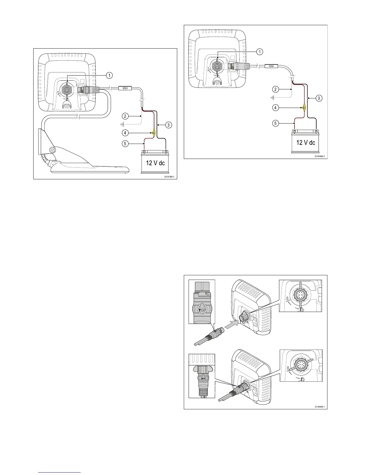
Theunithasacombinedpowerandtransducer
cablethatisattachedtothetransducer.
1.Connectthetransducer/powerconnectorto
therearoftheunitandsecureusingthelocking
collar.
2.Thedrainwireshouldbeconnectedtothevessel
RFgroundpoint.Ifyourvesselhasnoground
pointconnecttothenegativesideofthevessel’s
powersupply.
3.TheNegativewiremustbeconnectedtothe
negativesideofthe12Vdcpowersupply.
4.Afuseholder(notsupplied)MUSTbettedto
thepositivewireusingasuitablyratedinlinefuse
orbreaker.
5.Thepositivewiremustbeconnectedtothe
positivesideofthe12Vdcpowersupply.
5.4Connectingthepowercable-5M
1.Connectthepowercabletotherearofthedisplay
andsecureusingthelockingcollar.
2.Thedrainwireshouldbeconnectedtothevessel
RFgroundpoint.Ifyourvesselhasnoground
pointconnecttothenegativesideofthevessel’s
powersupply.
3.TheNegativewiremustbeconnectedtothe
negativesideofthe12Vdcpowersupply.
4.Afuseholder(notsupplied)MUSTbettedto
thepositivewireusingasuitablyratedinlinefuse
orbreaker.
5.Thepositivewiremustbeconnectedtothe
positivesideofthe12Vdcpowersupply.
Connectingthecabletothedisplay
1.Ensurethelockingcollarisintheunlocked
position.
2.Ensurethatthecableconnectorisorientated
correctly,rotatesothattheword‘TOP’isonthe
topofthecableconnector.
38
Dragony–4/Dragony–5/Dragony–7/Wi–Fish