Radarscannermountingangle
EnsuretheRadarscannerrotatesparalleltothe
waterline.
TheRadarbeamfromtheRadarscanneris
approximately20°wideintheverticaldirection,to
givegoodtargetdetectionevenwhenyourvessel
pitchesandrolls.
Planinghullvessels,andsomedisplacementhull
vessels,adoptahigherbowanglewhenthevesselis
atcruisingspeed.ThismayraisetheRadar’smain
radiationangle,andcancausepoordetectionof
nearbytargets.Itmaybenecessarytocompensate
forthebowrisetoensureoptimumtargetdetection.
Thiscanbeachievedbyttingawedgeorwashers
betweenthemountingplatformandthebaseofthe
Radarscanner,sothattheRadarbeamremains
paralleltothewaterlinewhenthevessel'sbowrises
atcruisingspeed.
ItemDescription
1Wedgeorwashers
MultipleRadarscanners—location
requirements
Importantlocationconsiderationswheninstalling
multipleradarscannersonthesamevessel.
•Scannersshouldbemountedaboveeachother,
verticallyseparatedbyatleast0.5m(1.6ft).This
appliestoallinstallationlocationsonthevessel.
•Multiplescannersshouldbemountedinaway
thatminimizesinterferencebetweenthevertical
beamwidthsofthe2scanners.
•Inallcases,youshouldaimtoachieveasmuch
physicalseparationaspossible,tominimizeany
potentialinterference.
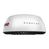
3.9QuantumWi-Fionly
installationrequirements
WhilsttheWi-Fiperformancehasbeentestedand
proveninmanydifferentinstallationscenarios,the
requirementsbelowmustbetakenintoconsideration
beforechoosingalocationfortheQuantum
™
Radar.
InsystemswithmultipleMFDs,theRadarshould
beconnectedtotheMFDsthatarelocatedclosest
toit,ortotheMFDswiththeclearestlineofsightto
theRadar.
ThemaximumdistancebetweenMFDandRadar
willvarydependingontheinstallationenvironment
(i.e.obstructionsandinterference).
Example1—Openair,lineofsightinoptimum
conditions
Inoptimumopenair,clearline-of-sightconditionsa
reliableconnectionispossibleatdistancesupto100
m(328feet).However,therearemanyfactorsthat
caninuencethissoapre-installationsitesurvey
shouldalwaysbeperformed.ForreliableWi-Fi
performancethesignalstrengthshouldbebetter
than–75dBm.Thecloserthesignalistozerothe
bettertheWi-Fiperformancewillbe(e.g.–40dBmis
betterthan–75dBm).Youcanassessthepotential
signalstrengthatthedesiredlocationduringthe
Pre-installationSiteSurveyusingaWi-FiAnalyzer
apponyoursmartdevice.
Example2—SignalpassingthroughFiberglass
coachroof
20
 Loading...