5.2Powercablerouting(Wi-Fi
variantonly)
Thereare2typicalpowercableroutingscenarios,
dependingonhowyourRadarissecuredtothe
vessel.
1.Platformmount.
2.Polemount.
Therecommendedpowercableroutingforthese2
scenariosisillustratedinthefollowingsection.
Platformmount
Routethepowercablethroughtheprovidedchannel.
Polemount
Routethepowercabletothesideoftheunittoallow
forthepolemount.
5.3Powerconnection
Note:AY-adaptercable(partnumberA80308)is
availableforexistinginstallationsthatalreadyuse
acombinedpower/datacablefromaDigitalorHD
ColorRadome.TheY-adaptersplitstheexisting
combinedcableintotheseparatedataandpower
connectorsusedbythescanner.
ItemDescriptionConnectsto:
1Powercable.Product’spower
connector.
2
Redcable(positive)
Powersupply’spositive
terminal.
3
Connectionto12V/
24Vpowersupply.
Powersupply.
4
Blackcable(negative)
Powersupply’snegative
terminal.
In-linefuseandthermalbreaker
ratings
Thefollowingin-linefuseandthermalbreakerratings
applytoyourproduct:
In-linefuseratingThermalbreakerrating
5A
3A(ifonlyconnectingone
device)
Note:
•Thesuitablefuseratingforthethermalbreaker
isdependentonthenumberofdevicesyouare
connecting.Ifindoubtconsultanauthorized
Raymarinedealer.
•Yourproduct’spowercablemayhaveatted
in-linefuse,ifnotthenyoumustaddanin-line
fuse/breakertothepositivewireofyour
productspowerconnection.
Warning:Groundingnot
required
Thisproductisfullyinsulatedanddoes
NOTrequireseparategrounding.
Powercableextension
Theproductissuppliedwithapowercable,which
canbeextendedifrequired.
•Thepowercableforeachunitinyoursystem
shouldberunasaseparate,singlelengthof
2-wirecablefromtheunittothevessel'sbatteryor
distributionpanel.
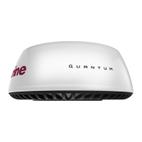
Cablesandconnections(QuantumvariantwithWi-Fi
only)
35
 Loading...