Do you have a question about the Raymarine hsb2 PLUS and is the answer not in the manual?
Introduction to the hsb2 Plus Series Fishfinder displays and their capabilities.
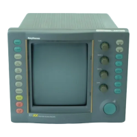
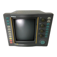
Overview of the basic components of the hsb2 Plus Series Fishfinder system.
Explains the High Speed Bus (hsb2) connection for data transfer between compatible units.
Describes the different display modes available for Fishfinder/Chartplotter units.
Details the graphical representation of echoes and status bar information on the Fishfinder.
Lists and briefly describes the various functions available for the Fishfinder.
Explains the chartplotter's functionality, navigation information, and status bar.
Details the functions available for the chartplotter, such as C-MAP data and route plotting.
Describes the various controls used to operate the fishfinder and chart systems.
Explains the function and use of the trackpad and on-screen cursor.
Details the functions of the dedicated, labeled control keys on the display unit.
Explains the function of the four soft keys whose labels change based on operation.
Provides installation instructions for the hsb2 Plus Series Fishfinders.
Considers factors for planning the system installation, including transducer and location.
Provides guidelines for optimum Electromagnetic Compatibility (EMC) performance.
Instructions for unpacking and checking all system components.
Guidance on selecting suitable locations for mounting the display unit.
Details on running system cables, including power, transducer, SeaTalk, and HSB cables.
Instructions for mounting the display unit using the supplied bracket or console kit.
Details on grounding the system and DC power connection requirements.
Describes the rear connectors for transducer, HSB, SeaTalk, NMEA, and Power/NMEA.
Explains how to link hsb2 Plus displays with other equipment for data transfer.
Details the High Speed Bus for rapid data transfer between master and repeater displays.
Describes receiving data via SeaTalk and NMEA, including connection details.
Guide to getting started with hsb2 Plus Series Fishfinder displays and controls.
Instructions for powering the display on/off and setting it as master or repeater.
Enables practice operation of Fishfinder/Chartplotter without external data.
Adjusting screen and key backlighting and contrast on monochrome displays.
Adjusting color palette, background, and brightness settings on color displays.
How to control the display using cursor and control keys.
Selecting between Fishfinder, Chart, or Data Log full-screen modes.
Functions for controlling the fishfinder display, like scroll speed and range.
Adjusting the speed at which the fishfinder display scrolls.
Selecting between 50 kHz, 200 kHz, or Split Frequency for sonar operation.
Using Bottom Lock to display a fixed-height water column referenced from the bottom.
Displays real-time sonar data showing bottom structure and fish directly below.
Enlarges all or part of the scrolling bottom display for detailed viewing.
Customizing chart features and screen presentation options for Raychart models.
Methods for panning, centering, and zooming the chart display.
Guide to maximizing the use of your Fishfinder and fine-tuning its image.
How to interpret fish and bottom indications and adjust the sonar image.
Describes how fish are displayed, including arch shapes and factors affecting them.
Explains how different bottom conditions are represented on the Fishfinder display.
Controls for GAIN, COLOR GAIN, and STC to reduce noise and adjust echo display.
Displays measurements in large format data boxes for specific information.
Setting alarms for fish, shallow water, and deep water conditions.
Using the Variable Range Marker (VRM) to measure depth and distance.
Details on placing waypoints in Fishfinder mode for navigation.
Instructions on how to place waypoints at cursor or vessel position.
Man Overboard function to return to a person or object's location.
Explains navigation using chart functions and covers topics like chart cards and waypoints.
Emphasizes checking route safety and comparing displayed objects with visual targets.
Details on using C-MAP NT/NT+ electronic chart cards for navigation.
How new chart information is displayed and accessed by repeater displays.
How to identify chart objects and obtain detailed information via pop-ups.
Covers placing, selecting, editing, erasing, and moving waypoints.
Step-by-step guide to placing waypoints using cursor or waypoint list.
Instructions on how to change a waypoint's name, symbol, and position.
Procedure for deleting waypoints, with caveats for routes.
Creating, saving, editing, and managing routes made of waypoints.
Step-by-step guide to creating a new route by placing waypoints.
How to save the current route to the database list and name it.
Guidance on following routes forwards, in reverse, and going to individual points.
Instructions for initiating and following the current route.
Methods for transferring waypoints and routes via SeaTalk, NMEA, or HSB.
Methods for maintaining database lists, including saving and loading from cartridges.
Functionality for marking and recording the vessel's trail on screen.
How to switch track on and specify the interval for track points.
Converts a track into a route, minimizing waypoints while maintaining correlation.
Explains additional functions like measuring distances, alarms, MOB, and radar overlay.
Obtaining accurate distance and bearing measurements between two points on the chart.
Setting various alarms like arrival, off track, anchor, and grounding.
Using the MOB function to return to a person or object lost overboard.
Detailed steps for placing a ruler line and using the VRM/EBL data box.
Reporting and setting chartplotter alarms like arrival, off track, and anchor alarms.
Initiating and canceling the MOB procedure, including display and data box information.
Enabling display of radar cursor on chart or chart cursor on radar picture.
Overlaying radar targets onto the chartplotter display for improved target identification.
Viewing GPS satellite status and tuning differential GPS to a beacon.
Logging course data, starting, stopping, and clearing log entries.
Guide to setting up the display for correct information, operation, and preferences.
Instructions for navigating and changing system, fishfinder, and chart parameters.
Lists system menus, options, factory defaults, and new default settings.
Selecting up to 6 data boxes for display on the fishfinder.
Setting the display mode for bearing and heading data (magnetic or true).
Choosing how the cursor readout is displayed: relative or magnetic/true bearing.
Controlling cursor data display in latitude/longitude or range/bearing.
Setting whether default soft keys are displayed during operation.
Controlling whether MOB data is based on position or dead reckoning.
Selecting Auto or Manual mode for variation values for heading/bearing.
Option to prevent NMEA heading data bridging onto the SeaTalk bus.
Disabling transmission of specific NMEA sentences when necessary.
Displaying cursors between radar and chartplotter displays.
Calibrating Raymarine heading sensors like Pathfinder Smart Heading System.
Allows operating the display without data for practice.
Setting up fishfinder parameters like target depth ID, color bar, and depth offset.
Setting up chartplotter parameters for system configuration and user preferences.
Information on routine maintenance and periodic checks for the display unit.
Periodic checks for cable damage and connector attachment.
Guidelines for cleaning the display screen and transducer safely.
Procedures for performing Factory, Power-On, and Picture Resets.
Identifying common problems and their solutions for the Fishfinder display.
Table listing common fishfinder issues and their corrective actions.
Information on contacting Raymarine for support, service, and parts.
General specifications including approvals, size, weight, power, and environmental limits.
Details on fishfinder features like output power, frequency, depth, and display modes.
Specifications for chartplotter features including cartography, scaling, and presentation modes.
Details on interfacing capabilities via High Speed Bus, SeaTalk, and NMEA.
Connection instructions for Raystar and Apelco GPS and Beacon Receivers.
Connection details for Autohelm GPS and Differential Beacon Receivers.
Specific connection instructions for the Raystar 112LP SeaTalk version.
Connection diagram for the Raystar 114 Combined GPS/DBR.
Connection details for the Raystar 120 WAAS Satellite Differential Receiver.
Lists chart features available on C-MAP cards, grouped by menu option.
Defines data received on NMEA/SeaTalk ports and their corresponding sources.