Do you have a question about the Raymarine hsb2 and is the answer not in the manual?
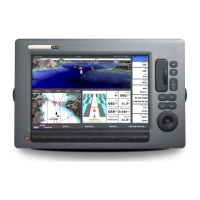
Provides an overview of the HSB Series LCD display and its features.
Details the radar picture representation, status bar, and customization options.
Explains chart display, navigation info, and control functions like zoom and pan.
Describes the trackpad, dedicated keys, soft keys, and pop-up menus for system operation.
Covers powering the unit on/off, radar/chart modes, and scanner states.
Details selecting operating modes (Radar, Chart, Data Log) and managing split screens.
Explains using zoom, offsetting the center, and hiding the ship's heading marker.
Covers moving charts, changing chart center, using FIND SHIP, and synchronizing radar/chart.
Explains radar range scales, changing range, and interpreting range rings.
Guides on interpreting echoes, adjusting gain, clutter, and tuning for optimal picture.
Details using VRM/EBLs for accurate measurement of range and bearing to targets.
Instructions for setting up radar guard zones and managing associated alarms for safety.
Introduction to MARPA for target tracking, risk analysis, and collision avoidance.
Explains radar display modes: Head Up, North Up, and Course Up.
Describes placing, moving, and deleting marks on the radar display.
Details initiating and using the MOB function to mark and navigate to a lost object.
Enables displaying cursors between radar and chart for enhanced data correlation.
Instructions for inserting, removing, and displaying data from C-MAP NT chart cards.
Covers placing, selecting, editing, erasing, and moving waypoints on the chart display.
Details creating, saving, editing, and following routes using waypoint sequences.
Explains setting up, managing, saving, and displaying vessel tracks on the chart.
Guide on measuring distances and bearings on the chart using VRM/EBL.
Information on setting up and reporting chartplotter alarms and timers for safety.
Details the MOB function for marking and returning to a lost person or object.
Instructions for setting up and tuning the GPS receiver for accurate navigation data.
Explains how to access and modify system, radar, MARPA, and chart parameters.
Lists and describes system parameters like data boxes, units, language, and variation source.
Details radar setup parameters for display, transmission, marks, and custom scales.
Options for configuring MARPA target vectors, safe zones, and target history display.
Configuration options for chart display, orientation, objects, vectors, datum, and position offset.
Lists all parts and accessories and provides instructions for checking them.
Guidelines for choosing the optimal mounting location considering convenience, access, and interference.
Instructions for mounting the display unit using a bracket or flush-mount kit.
Details on grounding, DC power connection, and powering external equipment.
Procedures for checking the radar installation and performing bearing alignment.
Explains connecting the HSB Series display to other equipment for data transfer.
Covers routine checks, cleaning procedures, and EMC servicing guidelines.
Provides common problems, their solutions, and contact information for support.
Provides general specifications for HSB Series 7" and 10.4" LCD Color Displays.
Lists detailed features and specifications related to the radar functionality.
Details the features and capabilities of the chartplotter functionality.
Connection details for specific GPS models to the auxiliary junction box.
Connection details for Autohelm GPS models to the auxiliary junction box.
Connection details for the Raystar 114 GPS/Beacon Receiver to the junction box.
Describes cartographic features and customization options for C-MAP chart cards.
Details data received and transmitted via SeaTalk and NMEA interfaces.
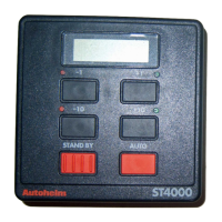
Configuration and connection details for integrating an ST80 compass with a course computer.
Configuration and connection details for integrating an ST80 compass with an autopilot.
Configuration and connection details for an ST80 system without a course computer.
Procedures for heading alignment and compass linearization for accurate heading data.
Lists alphabetical abbreviations used in the manual.
| Power Output | 4 kW |
|---|---|
| Type | Radar |
| Resolution | 640 x 480 pixels |
| Power Supply | 12V DC |
| Weight | Approx. 5 kg |
| Compatibility | Raymarine systems |
| Frequency | 9.4 GHz |
| Range | Up to 48 nautical miles |
| Antenna Length | 4 feet |