Chapter 8: Installation 8-1
Introduction
Chapter 8: Installation
8.1 Introduction
This chapter provides installation instructions for the HSB Series Color LCD
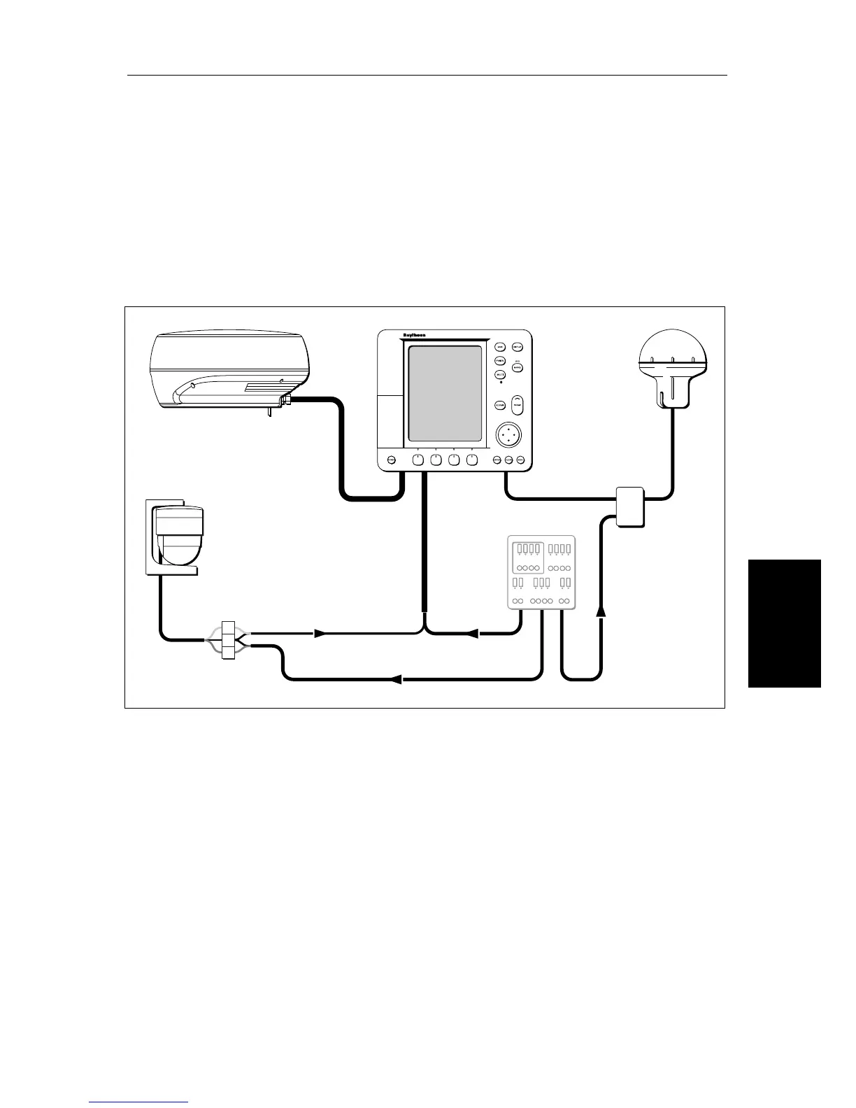
Display. Simple systems such as that in Figure 8-1 below, or integrated
systems (see Section 8.8) are explained. Details for mounting the HSB Series
LCD Display and connecting the equipment are included.
Figure 8-1: Typical System
Note:
If you wish to practice using the display before installation, connect a
12V or 24V DC power supply (connecting the red wire via a 6.3A quick blow
fuse to positive and the black wire to negative) and using the simulator mode,
as described in Chapter 2.
If you are connecting your display to other equipment (including another HSB
Series display unit) install then test the display as described in this chapter.
Details on installing the scanner are provided in the
Pathfinder Radar
Scanner Owner’s Handbook. Once the display is operating correctly, you can
connect it to other equipment as described in Section 8.8, taking particular
care to ensure the correct polarity of the SeaTalk supply. Section 8.8 describes
the HSB, SeaTalk and NMEA interfaces.
NMEA
SeaTalk
Display Unit
Distribution Panel
D4288-2
Scanner
12/24V Supply
12V Supply
12V Supply
Junction
Box
GPS
Compass