6.1Mountingpre-requisite:
"breather"holes
Thebaseoftheunitfeaturesa"breather",aseriesof
smallholeswhichallowairtocirculatebetweenthe
undersideoftheunitandthemountingsurface.
1.Locationof“breather”holes.
Ensurethatthebreatherisnotblockedinanyway.
Examplesofobstaclestoairowincludesealantand
paint.
Ifnecessary,useadditionalwasherstoallowa
smallgapbetweentheundersideoftheunitandthe
mountingsurface,forairow.
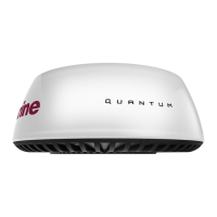
6.2Mountingthescanner
Useamountinglocationthat:
•IsrobustenoughtosupporttheQuantum
™
scanner,underseagoingconditions.
•MeetstherequirementsdescribedunderScanner
Position.
Then:
1.Tapethetemplatetothemountingplatform,
ensuringthatthearrowonthetemplateispointed
towardsthefrontofthevessel.
2.Drill3mmpilotholesinthefourpositionsshown
onthetemplate.
3.Drilloutthepilotholesto10mmdiameter.
4.PlacetheQuantum
™
scannerinposition.Ifyou
arettingitonaplaningvessel,shimtherear
ofthescanner,sothatthebeampointsslightly
downintheforwarddirectionwhentheboatisat
rest,tocompensateforthebowrisingatcruising
speed
ItemDescription
1
Mountingplatform,non-planingboat(levelinstall)
2
Mountingplatform,planingboat(typicalplaning
angleshown)
5.Beforesecuringthescannertothemounting
platform,connectthepowercable(andoptionally
adatacable),ensuringthatallcablesare
routedappropriately.Seethe4.3Connections
overviewsectionforfurtherinformationabout
makingconnections,andcablerouting.
40
 Loading...